Radio signal path loss is a particularly important element in the design of any radio communications system or wireless system. The radio signal path loss will determine many elements of the radio communications system in particular the transmitter power, and the antennas, especially their gain, height and general location. The radio path loss will also affect other elements such as the required receiver sensitivity, the form of transmission used and several other factors.
As a result, it is necessary to understand the reasons for radio path loss, and to be able to determine the levels of the signal loss for a give radio path.
Path Loss
Path loss is the loss of power of an RF signal travelling (propagating) through space. It is expressed in dB. Path loss depends on:
- The distance between transmitting and receiving antennas.
- Line of sight clearance between the receiving and transmitting antennas.
- Antenna height
Three kinds of path loss models are:
- Empirical models
- Semi-deterministic models
- Deterministic models
They can be briefly explained below:
- Empirical models : based on measurement data, simple (few parameters), use statistical properties, not very accurate
- Semi-deterministic models : based on empirical models + deterministic aspects
- Deterministic models : site-specific, require enormous number of geometry information about the cite, very important computational effort, accurate
Free Space Path Loss
In telecommunication, free-space path loss (FSPL) is the loss in signal strength of an electromagnetic wave that would result from a line-of-sight path through free space (usually air), with no obstacles nearby to cause reflection or diffraction. It is defined in “Standard Definitions of Terms for Antennas”, IEEE Std 145-1983, as “The loss between two isotropic radiators in free space, expressed as a power ratio.” Usually it is expressed in dB, although the IEEE standard does not say that. So it assumes that the antenna gain is a power ratio of 1.0, or 0 dB. It does not include any loss associated with hardware imperfections, or the effects of any antennas gain.
There are many reasons for the radio path loss that may occur:
- Free space loss: The free space loss occurs as the signal travels through space without any other effects attenuating the signal it will still diminish as it spreads out. This can be thought of as the radio communications signal spreading out as an ever increasing sphere.
- Absorption losses: Absorption losses occur if the radio signal passes into a medium which is not totally transparent to radio signals. This can be likened to a light signal passing through transparent glass.
- Diffraction: Diffraction losses occur when an object appears in the path. The signal can diffract around the object, but losses occur. The loss is higher the more rounded the object. Radio signals tend to diffract better around sharp edges.
- Multipath: In a real terrestrial environment, signals will be reflected and they will reach the receiver via a number of different paths. These signals may add or subtract from each other depending upon the relative phases of the signals.
- Terrain: The terrain over which signals travel will have a significant effect on the signal. Obviously hills which obstruct the path will considerably attenuate the signal, often making reception impossible.
- Buildings and vegetation: For mobile applications, buildings and other obstructions including vegetation have a marked effect. Not only will buildings reflect radio signals, they will also absorb them. Cellular communications are often significantly impaired within buildings. Trees and foliage can attenuate radio signals, particularly when wet.
- Atmosphere: The atmosphere can affect radio signal paths. At lower frequencies, especially below 30 – 50MHz, the ionosphere has a significant effect, reflecting (or more correctly refracting) them back to Earth. At frequencies above 50 MHz and more the troposphere has a major effect, refracting the signals back to earth as a result of changing refractive index. For UHF broadcast this can extend coverage to approximately a third beyond the horizon.
These reasons represent some of the major elements causing signal path loss for any radio system.
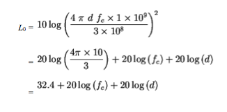
Derivation the dB version of the Path Loss Equation for Free Space
For free propagation waves in radio channel, the path loss model is
 (1)
(1)
Where  so
so

(2)
For d in meters , fc in GHz and![]() meters / second,
meters / second,

(3)
By taking ![]() of both sides of equation (3) to obtain the dB version
of both sides of equation (3) to obtain the dB version

Radio signal path loss can be caused by many factors. Only in the free space scenario is the calculation straightforward. In a terrestrial environment there are many factors that affect the actual RF path loss. When planning any radio or wireless system, it is necessary to have a broad understanding the elements that give rise to the path loss, and in this way design the system accordingly.
I am a final year btech ece student at RSET,Cochin


interested