


Similar to the infrastructure for passenger cars, chargers will be needed to charge commercial vehicles for several hundreds of kWh within the driver’s lunch break. Delivering 500 kWh in less than 30 minutes will require over 1 MW of charging power.

Current high-power charging standards include power levels up to 2.2 MW and can be expected to upgrade up to 4.5 MW in the coming years.

Recent solutions for passenger cars, based on fast-switching devices like IGBTs or SiC-MOSFETs, target power levels up to 350 kW but simply scaling up this approach may not be the best solution.
Topologies and technologies used for similar high-power DC applications such as electrolysis are better choices in terms of size, cost, efficiency, availability, and reliability.
This article explores an alternative high-power DC charging approach inspired by electrolysis applications, leveraging thyristor-based rectifiers.

Table of Contents
1. State-of-the-art High-Power DC-charging approach
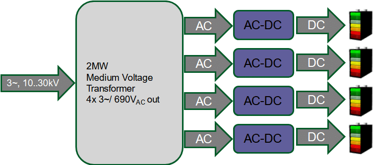
Many countries around the world have launched chargers that provide 350 kW for passenger cars. With charging parks along main routes that offer 6-10 chargers, the power can only be provided from the medium-voltage grid by means of transformers. A common structure for such a setup is depicted in Fig 1.
.
Fig 1: High-Power Charger supplied via medium-voltage transformer
Each of the chargers, respectively AC-DC-Converters, supports 350 kW by stacking units with lower output power.
Usually, these subunits remain in the range of 60 to 80 kW. A widely used approach consists of an input stage with boost- and PFC-functionality, followed by a DC-DC-converter in buck configuration to adapt the DC voltage to the battery’s requirements. A non-isolated and therefore more efficient design is sketched in Fig. 2.

Here, SiC-MOSFETs are implemented to further enhance efficiency. To achieve or exceed 60 kW of output power at high efficiency, each MOSFET in the diagram consists of at least 2 dies in parallel resulting in the use of no less than 28 MOSFETs in one subunit.
To build a single 350 kW AC-DC-converter, six of these units need to be paralleled.
The efficiency of such a non-isolated converter structure using SiC-based devices is mentioned to exceed 97% [1]. Though this is an achievement already, it also means that each subunit contributes 1800 W of losses, summing up to 10.5 kW for the complete setup.
Therefore, liquid cooling becomes a mandatory prerequisite for this approach.
2. High-Power Electrolysis
Electrolysis is a process in which bonded elements and compounds are dissociated by the passing of an electric current.
Electrolysis is used, for example, to extract metals, or to produce substances that would be more expensive or hardly possible to extract by purely chemical processes. Examples of important electrolysis processes are the extraction of hydrogen, aluminium, magnesium, chlorine, and caustic soda.
Recently, due to the attention given to green hydrogen production, electrolysis has become a prominent topic.
State-of-the-art in electrolysis
The forward voltage of a single electrolysis cell that separates water into hydrogen and oxygen is approximately 1.8-1.9 V, depending on the temperature and the chemical additives used to enhance the electrolyte. The Current densities in the electrolyte range up to 0.5 A/cm².
At 1000 A of DC-current, a cell featuring an area of 2000 cm² can be powered, generating roughly 1 kg of gaseous hydrogen per day.
The major similarities between electrolysis and battery charging come from the electrical settings.
The Prerequisite for an optimized process in these two applications is precisely controlled DC voltages and currents. The voltage is applied to a series connection of cells while the individual cell voltages add up to the DC voltage. The difference in detail lies in the single cell’s voltage level and the correlating U-I-characteristic.
From the chemical point of view, charging a battery is an electrolysis process itself.
For decades, the dominating topology used in high-power electrolysis is the thyristor-based 12‑pulse rectifier as sketched in Fig 3.
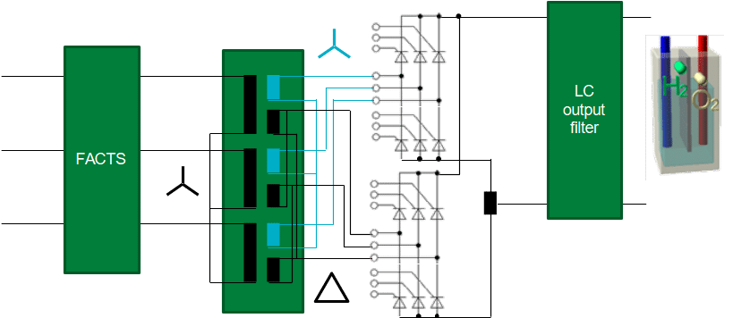
The core components are the transformer and the two independent B6C-rectifiers.
It is important, that the two individual 3-phase outputs of the transformer are phase-shifted by 30°.
Dedicated transformers to achieve this are the types Dy5Dd0 with a primary-winding scheme in delta-connection, as well as type Yy0Yd11 that offers a Y-structured primary-winding. In both cases, the secondary outputs of the two systems must be matched in regards of their voltage amplitude.
The two B6C bridges can be series-connected to support higher voltages and thus a larger number of cells in series-connection to be powered.
Alternatively, the bridges can be paralleled to increase the current in a given number of cells.
Major benefits of the topology include a very low voltage ripple of less than 3% when operating near the maximum output voltage and minimal impact on the primary side because only harmonics 12 times the grid frequency appear.
Typically, the voltage is adapted in a narrow band below the rated output. The example includes a 690 Vac output at the transformer which leads to a maximum DC voltage of 975 V for each of the rectifier stages. Adapting the voltage in a range to no less than 780 V keeps the power factor cos(φ) larger than 0.8 and thus in a regime that doesn’t need special attention in regards to reactive power compensation.
In electrolysis, this can easily be achieved by choosing a corresponding number of cells in the series connection.
To allow power levels to range down to 50%, reactive power compensation on the medium-voltage-side is needed. These represent an electrically and cost-efficient solution to make sure the setup adheres to the individual grid codes.
Being a single-stage AC-DC energy conversion, the setup has a proven track record of outstanding efficiency, availability, and longevity. The thyristor-based designs have been in permanent operation on site for decades and the press-pack devices involved have excellent capabilities in terms of power- and thermal cycling performance.
Channelling 2 kA through thyristors in a B12C demands a power component like the N1718NC200 [2].
A further improvement can be achieved by setting up such a structure in a so-called n+1 scheme. Here, a second thyristor is added in each position. Although this sacrifices efficiency, it adds redundancy to the system. Presspack devices offer the feature called “short on fail” and in case one thyristor fails, it fails short. Due to the fact that the forward voltage drop can be detected, maintenance can be preventively scheduled while the rectifier remains operational with no loss in performance.
3. Thyristor-based High-Power Charging
One energy conversion stage is removed by changing from fast-switching devices to a controlled direct AC-DC-approach and the use of thyristors literally eliminates the switching losses. Both lead to increased efficiency, boosted by the non-linearity of the bipolar power semiconductor.
From the N1718NC200’s datasheet, the forward voltage can be extracted to be 1064 mV at 500 A, growing to 1148 mV at 1000 A. This represents an equivalent resistance of 1.15 mW only. holds the related on-state characteristics.

Evaluating the thyristor in use by PLECS-simulation reveals, that after ramping up to IT=1000 A, the losses in each of the rectifiers’ semiconductors grow to 384 W. The simulated ramp-up result can be seen in Fig. 5.

With 384 W per thyristor, the twelve devices only contribute 4600 W of losses while the output power is 2.5 MW. This indicates an efficiency of 99.8%, which is a key factor in the transition from liquid cooling to forced-air cooling.
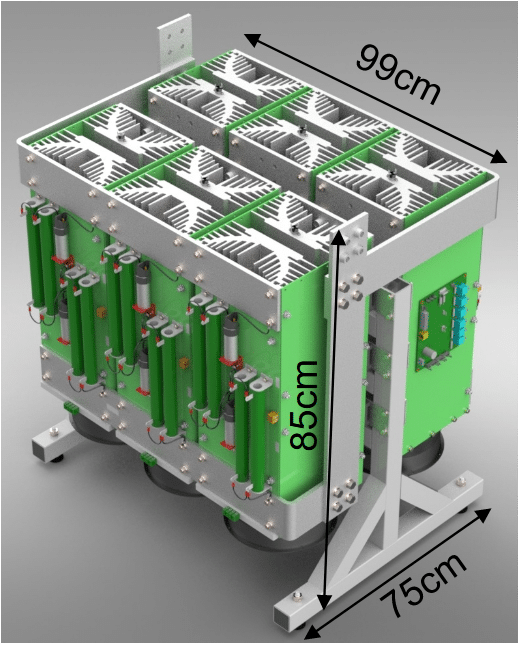
A stack containing the two independent B6C bridges was designed and built to evaluate mechanical features as well as size and material content; the rendering is depicted in Fig. 6.
In addition to the excellent efficiency, the weight, volume, and complexity of the final system are also greatly reduced.
4. Comparing SiC-MOSFET and Thyristor as core components in a 2.5 MW installation
Fig. 7 is a comparison of the necessary components with all parts drawn to the scale.

The comparison is based on the fact, that a SiC-MOSFET-based 60 kW system as described in fits into an industrial 19’’-rack and has dimensions [W/H/D] of 483 mm x 90 mm x 880 mm.
With 75 kW of losses, liquid cooling demands a chiller to handle that much thermal energy. Based on experience, 1/3 of that power is needed on the electrical side to extract this heat.
Thermal management on the thyristor stack is limited to forced air cooling using six fans, each with 100 W.
An overview of further important parameters describing the 2.5 MW system is summarized in Table 1.
Table 1: Comparison of the two different solutions in numbers
| SiC-MOSFETs | Thyristors | |
| Nr. of subunits | 42 | 1 |
| Nr. of power semiconductors | >1100 | 12 |
| Nr. of AC connections | 126 | 3 |
| Nr. of DC connections | 84 | 2 |
| Weight | unknown | 370 kg |
| Built volume | 6m³ | 0.6m³ |
| Connections for liquid cooling | 84 | – |
| Efficiency | 97% | 99.7% |
| Losses @2.5 MW throughput | 75 kW | 7.5 kW |
| Cooling power | 25 kW | 0.6 kW |
An increase in efficiency by 2.7% may not look like a big difference in the first place. Looking at it from a different perspective, this does mean there is a 90% loss reduction within the system. This in turn has a massive impact on the application in hardware due to the necessary liquid cooling. It also heavily impacts the operational cost for the charge-point operators.
Considering projects like [3], targeting to set up 1700 installations with MW-capable hardware, both energetic as well as financial losses due to inefficiency grow intolerably.
If each of the chargers operates 24/7 and handles three vehicles per hour, 10 minutes each to transfer 400kWh, the energy consumption and losses as given in Table 2 result.
Table 2: Comparing SiC-MOSFET and Thyristor-based solutions regarding cost of operation
| Liquid Cooling, SiC- MOSFET | Forced-Air cooling Si- Thyristors | ||
| Cooling | Power per charger [kW] | 25 | 0.6 |
| Energy per year per charger [kWh] | 109500 | 2628 | |
| Energy cost per charger [€/year] @ 0.1€/kWh | 10950 | 263 | |
| Money spent, 1700 chargers [€/year] | 18.615.000 | 447.1400 | |
| Operation | Losses, single charge [kWh] | 12.5 | 1.25 |
| Energy lost in 1700 chargers per year [kWh] | 558.450.000 | 558.450 | |
| Losses in 1700 chargers per year [€] | 55.845.000 | 5.584.500 | |
| Money saved per year [€] | – | 64.510.972 |
As a side note, there also is an environmental penalty as each kWh of electricity is burdened with a CO2 footprint. With about 0.5 kg CO2/kWh, almost 280.000 tons of CO2 generation can be prevented.
These numbers grow rapidly if autonomous vehicles are considered and the chargers utilization increases beyond the 50% assumed in this scenario. If the output power of the charger increases to the maximum limit given by the standards, the same applies.
Conclusion
Electrification of heavy-duty vehicles is a mandatory step towards emission reduction in traffic. Although the efficiency of electric motors is significantly improved compared to their combustion-engine counterparts, striving for maximum efficiency in the supporting infrastructure becomes an important part of the game.
At the infrastructure scale, efficiency becomes an even more important factor, as the amount of energy potentially lost may have a negative impact on the entire economy. It is to be noted that care should be taken to not simply scale up an existing solution but to build the infrastructure based on considerations that include efficiency, availability, and longevity as well.
In detail, this demands to review all available options to ultimately choose the most suitable one, even if that is not the most recent, fancy or hyped one.
An efficiency below 100% is a clear sign, that there is room for improvement.
References
[1] Infineon Technologies: Herausforderung Schnell-Ladung, Effiziente Gleichstromschnellladestationen mit Ladeleistungen bis 350kW im Smart-Grid der Zukunft
(The Fast-Charging Challenge, Efficient DC-Fast-Charging stations with charging power up to 350kW in future smart grids) Freiburg, October 2019
[2] Data sheet, N1718NC200, Issue 4
[3] Daimler, Volvo and Traton plan $600 million truck-charging JV visited July 28, 2021
Author: Dr. Martin Schulz, Global Principal Application Engineer, Littelfuse
Dr. Martin Schulz joined Littelfuse in February 2021 as Global Principal in Application Engineering. He is responsible for power semiconductors for electric commercial vehicles, charging infrastructure, energy storage systems and industrial drive technology. He is an expert in packaging and interconnect technology in power semiconductors as well as in thermal management of power semiconductors. Martin Schulz has more than 20 years of experience in the field of power electronics and is a Senior IEEE-Member.