This calculator helps you determine the values of the resistors R1 and R2 to be used for a T-pad attenuator.
Inputs
Outputs
A T-Pad Attenuator is a passive three-port circuit used to reduce the power of a signal without distorting its waveform. It is commonly used in RF and audio systems to adjust signal levels while maintaining impedance matching. The T-pad consists of two resistors in series and one resistor to ground, arranged in a “T” configuration.
The Free Online T-Pad Attenuator Calculator helps you easily calculate the required resistor values for a specific level of attenuation, making it easier to design efficient attenuation circuits for various applications.
Why Use This Calculator?
The T-Pad Attenuator Calculator offers several benefits for engineers and designers working with signal attenuation:
- Quick and Accurate Calculations: Instantly calculates the resistor values needed for the T-pad attenuator based on your desired attenuation and impedance values.
- User-Friendly: Simple interface that allows easy input of desired parameters like attenuation and impedance, providing quick results.
- Flexible Application: Can be used for both high-frequency RF systems and audio applications, making it versatile for a range of industries.
- Ensures Impedance Matching: Helps in maintaining proper impedance matching between different components in your system, preventing signal reflections and losses.
- Free and Accessible: Available online for free with no installation required, making it a convenient tool for quick calculations.
How to Use the T-Pad Attenuator Calculator
Using the Free Online T-Pad Attenuator Calculator is straightforward:
- Enter the Desired Attenuation (in dB): Input the level of signal attenuation you want for your circuit.
- Specify the Input and Output Impedance: Provide the values for input and output impedance, typically 50 ohms for RF systems or other values depending on your specific requirements.
- Click Calculate: The calculator will output the resistor values (R1, R2, and R3) required for the T-pad attenuator configuration.
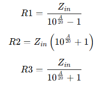
The T-pad attenuator is typically designed using the following equations for calculating the resistor values:

Where:
- A = Attenuation in dB
- Zin = Input impedance (ohms)
The T-pad attenuator works by calculating three resistors based on the desired attenuation and the input/output impedance. The formulas used to calculate the values of these resistors are as follows:
- R1 is the series resistor, controlling the overall level of attenuation.
- R2 is the shunt resistor, placed between the signal line and the ground.
- R3 is the second series resistor, matching the impedance between the output and the ground.
The resistor values are determined using the desired attenuation level in dB, and the input/output impedance of the system, ensuring minimal signal loss and optimal impedance matching.
Applications of the T-Pad Attenuator Calculator
The T-Pad Attenuator Calculator is useful in several applications:
- Signal Level Adjustment: Used to reduce the amplitude of a signal in audio and RF systems while maintaining signal integrity.
- Impedance Matching: Ensures proper impedance matching between devices like amplifiers, antennas, and transmission lines, preventing reflections and power loss.
- Test and Measurement: Essential in test equipment for adjusting signal levels without introducing distortion, allowing for accurate measurements.
- RF Network Design: Helps in designing attenuators for RF circuits to control power distribution and minimize signal interference.
- Audio Systems: Used in audio systems to balance signal levels between different components, like preamps, mixers, and amplifiers.
Also Check:
- Balanced Attenuator Calculator
- Pi Attenuator Calculator
- Bridged-Tee Attenuator Calculator
- Reflection Attenuator Calculator
Check Electronics Calculators that you can use for free.


