


In this series we shall be just scratching the surface of the iron-air battery saga. Their promise sparks a crucial question: Can this unassuming metal redefine our energy landscape?
Lithium-ion batteries are utilised every day for torchlights to electric vehicles. However, global electric power generation is measured in gigawatts. Fossil fuel power stations are being phased out in favour of cheap, clean, and renewable energy, but they are very vulnerable to the vagaries of nature. A key roadblock for renewable energy to be viable is a long-term and reliable grid energy storage system, which cannot be adequately fulfilled by the current battery technology. Next-generation iron-air battery technology could revolutionise energy storage, unlocking tens of gigawatts of demand at any time from multiday grid storage systems using iron-air batteries.
Today, lithium-ion batteries are found in consumer products for energy storage. However, what works in a laptop is not the best solution for power grids, where energy output is measured in megawatts. Lithium-ion batteries perform well when consuming energy over a short period.

Researchers believe that this problem can be solved by employing iron-air batteries. Each battery, approximately the size of a washing machine, consists of about 50 iron-air cells. These cells breathe in air, transforming the iron into rust (iron oxide) and producing energy. During charging, the current reverses the oxidation, reducing iron oxide back into iron.
The primary task of these batteries is to bridge the gap when utilities need more power during peak periods. They can store excess energy on sunny days to supplement supply on cloudy days. While lithium-ion batteries provide four hours of storage, iron-air batteries can deliver up to four days to bridge the gap, and they are cost-effective.
History
Metal-air batteries were first designed in 1878. This technology uses atmospheric oxygen as a cathode (electron receiver) and a cheap metal anode (electron giver) made of iron, aluminium, or zinc. In 1932, zinc-air batteries were the first type of metal-air battery widely used in hearing aids.
Three decades later, NASA developed iron-air batteries and created batteries with a 50-20Ah charge capacity capable of achieving less than 200 cycles with an energy density of 132-154Wh/kg.
They also reported that batteries involving air were more problematic due to difficulty in recharging. Oxygen reacts with the metal, creating a chemical that triggers the electrolysis process of discharging energy. Due to constant airflow, the battery would corrode quickly even when left unused, resulting in a very short shelf life.
The main advantage is that no metal dendrites are formed during charging. On the other hand, hydrogen is formed in substantial quantities.
The technique was utilised by the Swedish National Development Electric Corporation in 1977 to produce a 30kWh battery for traction applications with an energy density of 80Wh/kg at the 5-hour rate. Subsequently, in 1980, Westinghouse Electric Corporation used modified, improved iron sintered electrodes which could be made in modules of 400cm² electrode area with a specific energy of 140Wh/kg that could achieve 1000 cycles.
Renewed interest has been growing in iron-air battery technology over the last few years due to tremendous advancements in nanotechnology. Now it is possible to use nanostructured catalysts and higher surface area iron (Fe) nanoparticles in electrodes. With these techniques, Fe-air batteries can be made to realise a higher energy density.
How it works
The basic principle of operation of an iron-air battery is reversible rusting, as shown in Fig. 1. While discharging, the battery breathes in oxygen from the air and converts iron into solid metal oxide, i.e., rust. While charging, the application of an electrical current converts the rust back to iron, and the battery breathes out oxygen.
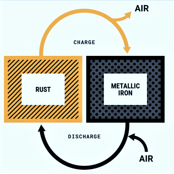
The energy itself is stored in the rust since that is a bond between iron and oxygen. The device’s fundamental working concept is to electrochemically reduce oxygen from the air and oxidise the metal electrode, resulting in the formation of solid metal oxides which can be recycled.
Let us look at Fig. 2 to understand the process in simple language. When discharging electricity, the battery inhales oxygen from the air and converts pure iron into rust. This allows electrons to flow, as seen on the right side of Fig. 2. As the battery is charged, the rust exhales oxygen, and oxygen exits as bubbles. Rust, i.e., oxides of iron, converts back to iron. The battery relies on this reverse rust cycle to ultimately store electricity at one-tenth the cost of a lithium-iron battery, as claimed by Form Energy, the developer of this technology.
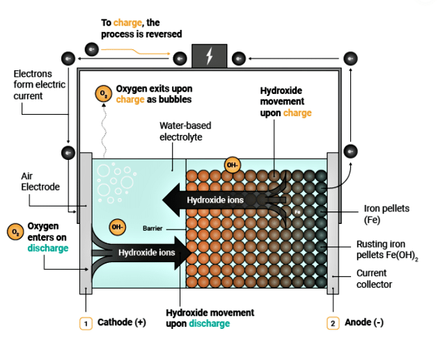
In Fe-air batteries, Fe changes into ions on the anode, while oxygen transforms into hydroxide ions at the cathode, as shown in Fig. 3. The utilisation of oxygen from the ambient air has the benefit of lowering the cost and weight of the battery considerably. The device consists of three components, namely an anode, a cathode, and an electrolyte.
Metallic iron is used as the anode, which is the negative electrode. The chemical activity of the anode determines the discharge capacity of the anode. Because of the high activity of the metal, a side reaction with various components of the electrolyte may occur and may affect the battery efficiency.
Anodes made of iron are compatible with aqueous electrolyte, facilitating ion transfer between two electrodes, i.e., cathode and anode. An oxidation reaction, i.e., electron loss, occurs on the anodic electrode. The released electrons, having gained excitation, become mobile and flow through a circuit to the cathodic electrode, where reduction occurs.
On the other hand, charges flow freely between the electrodes of the battery via the electrolyte. While iron anodes are compatible with aqueous electrolytes, the system requires a hydrophobic protective layer to prevent electrolyte leakage.
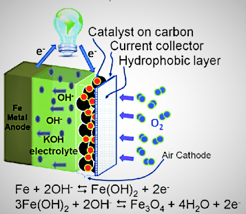
The cathode is the third part of the battery, and the active material for the cathode is oxygen from the air, which is freely available. It does not require any hefty shell to contain it, increasing the device’s efficiency. The air cathode generally consists of a gas diffusion layer that absorbs oxygen from the air, a catalyst layer that enhances the ORR (oxygen reduction reaction) and OER (oxygen evolution reaction), and a current collector that connects the battery to external electrical circuits to create a closed circuit. The schematic arrangement of the Fe-air battery and its electrochemical reaction is shown in Fig. 4.
Attractive features
Metallic iron can be used directly as an anode in aqueous electrolytes due to its appropriate redox potential of -0.44V vs SHE (standard hydrogen electrode) in an acidic solution and -0.88V vs SHE in alkaline electrolyte. Redox potential is a measure of how easily a substance loses or gains electrons in a reduction-oxidation reaction. Aqueous Zn-ion batteries are one of the most attractive battery systems. However, as the redox potential of Fe is higher than that of Zn, it exhibits better stability in aqueous electrolyte than Zn. The theoretical specific capacity and volumetric capacity of Fe are about 960mAh g-1 (820mAh g-1 for Zn) and 7557mAh cm-3 (5851mAh cm-3 for Zn), respectively.
These properties enable Fe-air batteries to have a higher specific capacity than Zn-ion batteries. The price of iron is 1/43 that of zinc. Unlike other batteries, iron is less prone to forming dendrites with repeated charge-discharge cycles, which can severely disfigure the electrode shape.
Compared to iron-nickel batteries, the weight of this battery can be decreased by one third, as it uses a lightweight bifunctional air-breathing electrode instead of a bulky positive nickel electrode. This step increases its specific energy by up to 100%. Iron is also a very low-cost metal, although the strong alkaline electrolyte requires necessary safety measures. Another advantage is that it has a good energy density of about 600Wh kg-1 with a round trip efficiency of about 90%, comparable to a Li-ion battery. Its estimated manufacturing cost is about $25/kWh, whereas the selling price of Li-ion batteries is about $200/kWh. The cycle life of the advanced Fe-air battery using ionic liquid as an electrolyte additive stands at more than 1000 cycles without showing any deterioration in capacity.
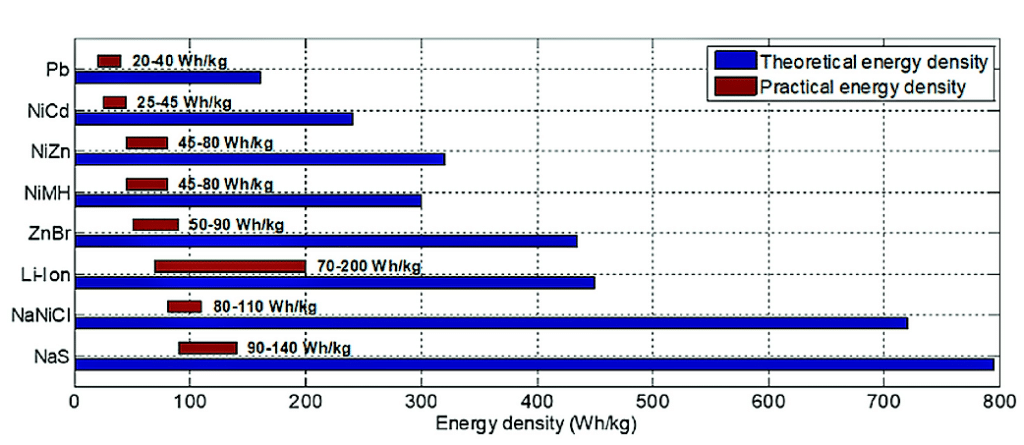
Iron-air batteries likely have a theoretical energy density of about 1200Wh/kg, whereas Li-ion batteries come in about 460Wh/kg. When expressed in volumetric energy density, the figure is quite impressive at 9700Wh/l, which is almost five times as high as that of Li-ion batteries (2000Wh/l). The theoretical and practical energy densities of various types of batteries are shown in Fig. 5.
Cell reaction
In Fe-air batteries, most of the products formed during cell reactions are solid, rather than being dissolved in the electrolyte, and there is no dendrite deposition. This makes the fabrication of the battery much simpler, as no separator is required to prevent dissolved metal species from reaching the air electrode.
In many cases, the circulation of electrolyte is not needed inside the cell to ensure the uniform electrodeposition of iron during recharging or to prevent dendrite deposition, except to remove excess heat and replenish the electrolyte. Fe-air cells usually deploy an aqueous KOH solution at 3-6 mol dm-3 to ensure good ionic conductivity and enable the reduction and evolution of oxygen reactions easily on the bifunctional catalyst of the oxygen electrode. The solubility of the iron oxide products is very low in an alkaline solution, making the solid-state iron electrode very stable. It is necessary that the catalytic surface of the air electrode is wetted with the electrolyte, but at the same time, the gas diffusion layer remains dry to allow facile oxygen diffusion towards the catalyst layer without any hindrance.
The oxidation of the iron electrode during the discharging cycle involves the following steps:
1. Fe+2OH–<——>Fe(OH)2+ 2e–, E0 (standard redox potential)= -0.88V vs. SHE (standard hydrogen electrode)
2. Fe+3OH–<——>HFeO2–+ H2O+2e–
3. HFeO2–+H2O<—–>Fe(OH)2 +2OH–
4. Fe(OH)2+OH–<——>FeOOH +H2O+e–, E0=-0.56V vs SHE
5. 3Fe(OH)2+2OH–<——>Fe3O4 +4H2O+2e–, E0=-0.66V vs SHE
6. 2Fe3O4+2OH–<—–>3Fe2O3 +H2O+2e–, E0=-0.60V vs SHE
7. 2H2O+2e–<——->H2+2OH–, E0=-0.83V vs SHE
The reverse reactions represent the charging half cycle.
The discharge reaction at the positive air electrode involves four electrons as shown below:
O2+2H2O+4e–<——>4OH–,
E=+0.401V vs SHE
The overall cell reaction is then:
3Fe+2O2<—–>Fe3O4
Reactions 1 to 3 shown above are desired capacity-generating reactions in the iron electrode with a theoretical capacity of 960mAh g–1. First, the iron is oxidised from metallic iron in the alkaline electrolyte to 2+, then further oxidised to a 3+ state. Further discharge converts iron to oxyhydroxide shown in reaction 4 and magnetite as per reaction 5, requiring higher overpotential.
Magnetite is hard to reduce to metallic iron and is less conductive than Fe metal. This increases the internal resistance of the cell, resulting in a large overpotential during charging.
Apart from these reactions, the evolution of hydrogen may also take place at open circuit voltage (OCV) because iron is unstable thermodynamically in an aqueous system. The standard hydrogen evolution reaction (HER) potential is 40mV positive to the iron electrode’s OCV. The iron electrode undergoes self-discharge due to the corrosion process and lowers the faradic efficiency and water loss in the system. Hence, overcharging and electrolyte top-up are necessary.
These problems can be overcome by adding small quantities of additives in the electrolyte that suppress hydrogen evolution and raise the overpotential of the iron electrode, decreasing the electrode resistance.
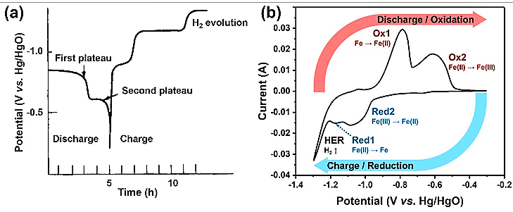
Fig. 6 shows a typical discharge/charge and CV curve of the iron anode in alkaline electrolyte.
The first and second plateaus shown in Fig. 6(a) are during the discharge cycle of a typical iron metal battery, corresponding to the oxidation of Fe0 to Fe2+ and Fe2+ to Fe3+, respectively. The cyclic voltammetry (CV) curve shows two pairs of major peaks at -0.79/-1.17V (Ox1/Red1) and at -0.62/-1.09V (Ox2/Red 2).
The first oxidation peak, i.e., Ox1, occurs during the formation of Fe(OH)2 as per reaction 1 shown earlier. The corresponding reduction peak, i.e., Red1, is accompanied by a steep peak indicating that parasitic hydrogen evolution reaction (HER) occurs. The second peaks (Ox2/Red2) correspond to complex transitions between Fe2+ and Fe3+, forming FeOOH, Fe3O4, Fe2O3, etc. The generation of irreversible Fe2O3 causes passivation leading to capacity reduction and ultimately failure.
The reaction that generates hydrogen is not desirable as it limits the oxidation reaction, but it stops when Fe3O4 is formed. In fact, the electrode reactions at the iron electrode are complex and still a matter of speculation owing to solid-state transformation within the surface film, and it is thought that several intermediates occur during charging and discharging.
In simple terms, during the discharge of the battery, metallic iron is converted to magnetite (Fe3O4), and it transforms back to metallic iron as the battery is recharged. During discharging, Fe changes into ions on the anodic electrode, while oxygen transforms into hydroxide ions at the cathodic electrode. The diffusion of oxygen into the battery occurs through the gas diffusion layer.
During the transition of Fe into metallic ions, electrons are produced. Metallic ions subsequently dissolve into the electrolyte. All these steps are reversed during charging.
The major problems faced by the iron electrode with alkaline electrolytes are the hydrogen evolution reaction and the formation of insulating iron hydroxide during charge-discharge processes. Usually, while charging an iron electrode, water is decomposed to produce hydrogen, and consequently, an amount of the energy that was supposed to be stored in the battery is wasted as a result of parasitic hydrogen evolution.
Additives like Bi2S3, K2S, or aliphatic sulphides may be added to the iron electrode to increase the charging efficiency, increase the porosity of the iron powder, and decrease the effect of the passivating layer. Another approach to restrain these drawbacks is by adding ionic liquid (1-methyl-methylimidazolium L-(+)-lactate (EML) as an electrolyte additive to suppress both hydrogen release and passivation formation on the electrode surface during battery discharge by forming iron lactate instead of iron oxide. As a result, the Fe-air battery achieves capacity retention of more than 94% after 1000 cycles.
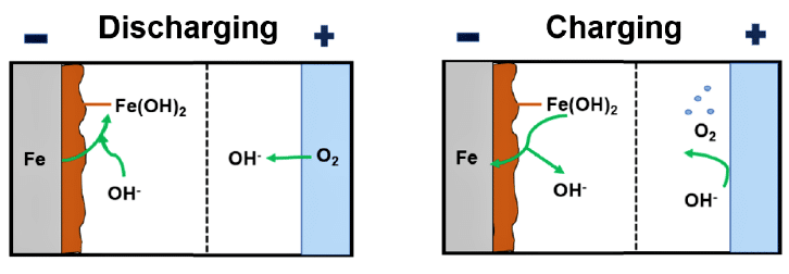
During charging, the OH– ions are oxidised, and oxygen bubbles out on the air electrode. During discharging, oxygen diffuses into the air electrode, and is reduced, generating OH– ions.
Oxygen evolution reaction (OER) and oxygen reduction reaction (ORR) involving four electrons’ transfer are important aspects of Fe-air batteries as shown in Fig. 7.
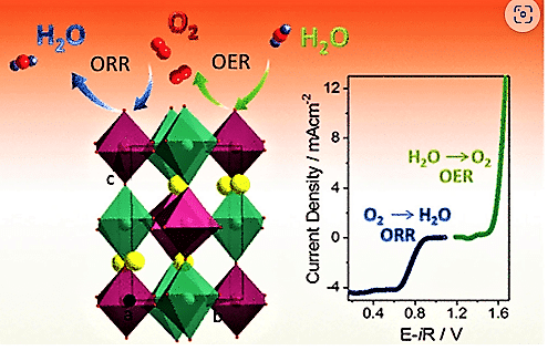
OER reaction is:
2H2O ——>O2+4H++4e–
ORR reaction is:
O2+4H++4e–———>2H2O
Due to the slow reaction kinetics of electrochemical reactions in Fe-air battery, it is necessary to use a bifunctional catalyst to speed up the reaction during charging and discharging operations. Perovskite families, noble metal groups like Pt, Pd, and Ru prefer the direct 4e– pathway, whereas the indirect two-electron pathway is favoured by carbon materials, transition metals, and oxides.
ORR at air electrode follows the following steps:
1. Oxygen from atmosphere is transferred to the catalyst surface.
2. And then it is absorbed on the active site.
3. Electrons are transferred from the catalyst to oxygen, followed by weakening and removal of the oxygen bond.
4. Finally, the catalyst surface releases the hydroxide ions to the electrolyte.
Design features
To date, most attention has been paid to zinc metal batteries, hoping to capitalise on zinc metal’s high capacity of ~820mAh g–1 and its low redox potential of -0.76V versus standard hydrogen electrode (SHE). Iron possesses attractive electrochemical properties. Via the two electron transfer, iron theoretically delivers a high specific capacity of ~960mAh g–1 and an outstanding volumetric capacity of ~7557mAh cm–3, both of which are higher than zinc. Its redox potential is -0.44, which is 0.3 volts higher than zinc, meaning that its stability in aqueous electrolyte is better. It is also cheap.
All these plus points are the driving force to renew the interest in iron-air batteries. Researchers have now made a viable iron-air battery that is capable of competing with other conventional storage batteries. The exploded view of the iron-air battery developed recently is shown in Fig. 8.
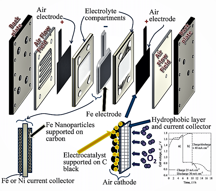
The main features of an iron-air battery consist of each metallic iron anode coupled with two air-breathing electrodes on each side, in a plane parallel configuration. The solid-phase discharge products are deposited on the anode surface and do not transport to the cathode side. The popular approach is to use powdered materials of iron or iron oxides supported by conductive material to fabricate iron electrodes. Polymer-based separators are generally used.
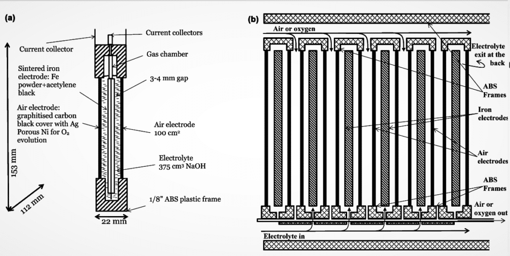
The air electrode is porous and has enhanced electronic conductivity via carbon-based materials, good ionic conductivity, and gas-phase operation. The air electrodes are designed to achieve both the evolution and the reduction of oxygen during the charge and discharge cycles, respectively. The electrode material should be able to withstand the high positive potential during oxygen evolution, must be electrochemically stable, and at the same time able to catalyse the reduction and evolution of oxygen with minimal overpotential losses. Fig. 9(a) shows the sectional arrangement of a single cell, and Fig. 9(b) represents a six-cell configuration.
To be continued…
Rathindra Nath Biswas is a 1964-batch chemical engineering graduate from Jadavpur University, Kolkata. He was awarded a certificate for designing Benzol Plant by Giprokoks, USSR, and Certificate of Honour by Indian Institute of Metals. He has published 35 research papers in various journals. He retired from service as Head – MECON, Durgapur.

