“One possible method to obtain a noise-free response would be to first make measurements on a network analyser and then use the response of the cable and de-embed that in the oscilloscope,” adds Bhatia. [De-embedding is an attempt to make the port as ideal as possible, similar to a calibration of a radio frequency (RF) measurement system with probes or connectors used for measurement].
A precision cable, or precision probe, can be used in order to get rid of the anomalies caused by a regular cable or probe, and hence bypass the process of using an analyser. Bhatia says, “In our oscilloscopes, we have a built-in simple, mini network- analyser feature, which measures the response of the cable, or probe, by generating a high-speed pulse, and the insertion loss of the cable is measured up to double bandwidth of the scope.” He adds, “The measurement performed by the scope is used to compensate for the loss with calculations done by the software. This unique feature can be used to measure the insertion loss in the time domain, which is ultimately converted into frequency domain.”
Use software packages for performing different kinds of analyses
Naresh Narasimhan, country marketing manager, Tektronix India, says, “Engineers are increasingly customising their general-purpose oscilloscopes via software packages that are now available with many oscilloscopes in this class.” For instance, software applications, such as various serial decode packages, vector signal analysis (VSA) software, power application and offline viewing and analysis software, allow users to customise and use their general-purpose oscilloscopes in a very specific manner.
“SignalVu VSA software, from Tektronix, that runs on the company’s various oscilloscopes series, has been enabling engineers to easily characterise and validate wideband and microwave spectral events,” says Narasimhan. He adds, “SignalVu-PC VSA software helps one to easily validate wideband designs.”

The latest generation of oscilloscopes are also coming with Windows 7 embedded operating system (OS) platform today. Bhatia says, “With Windows 7 embedded OS comes the advantage of writing advanced software, thereby providing high analysis capabilities, such as jitter analysis or mathematical functions. New user interfaces are also powering Windows based scopes, which help users customise by creating a large number of windows, grids and mathematical functions on the screen of the oscilloscope.” These windows can be resized as per requirements. He adds, “For instance, some people prefer having very big measurement windows and a small waveform window, and vice-versa.”
Also, for ease of use, the actual vertical scale is printed on the oscilloscope’s screen. Normally, if the user has switched the scale to one volt/division and the waveform is seen across three divisions each from the central axis, it is interpreted as six volts by looking at the divisions and scaling, informs Bhatia. He says, “With scaling numbers printed on the screen in time and voltage, it makes it quick and easy for the user to interpret data.” Such advanced and powerful OSes are slowly trickling down to low-end oscilloscopes as well.
Use digital trigger for precise measurements
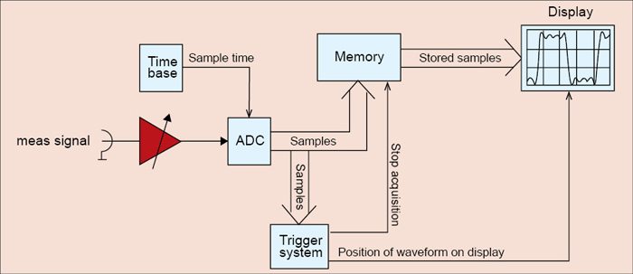
The trigger is a key element in the scope. It allows capturing events of interest to provide a detailed analysis and ensuring a stable display for repeating signals. Traditional digital oscilloscopes implement analogue triggers, which means acquisition and trigger paths are different.
“The industry’s first digital trigger is implemented by Rohde & Schwarz in their RTO and RTE series of scopes. In a digital trigger, the trigger signal is derived from samples of analogue-to-digital (A/D) converters. Therefore the digital trigger processes an identical signal that is acquired and displayed,” shares Srinivasa Rao Appalla, manager, product support and applications, Rohde & Schwarz. He adds, “The digital trigger offers very low trigger jitter in real-time, combined with high-acquisition and analysis rates in RTO and RTE scopes. It enables precise measurements due to high trigger sensitivity at full bandwidth and adjustable digital filter for the signals.”

Fig. 1 shows a block diagram of digital trigger implementation.
Use advanced maths operators for better power analysis
Modern oscilloscopes have powerful analysis and software capabilities; in particular, they have a lot of maths functions. Add, subtract, multiply, divide, differentiate, integrate, fast Fourier transform (FFT), square-root, absolute value, logarithms, filters and many more transforms and operators are available. You can apply these operators on captured data, and it shows you the result not only in stop mode but real-time as well. Some oscilloscopes also allow users to enter and edit formulae to actively perform advanced calculations. It is practical in various applications such as power analysis by using operators (such as integral to find out power consumption of a microcontroller).


