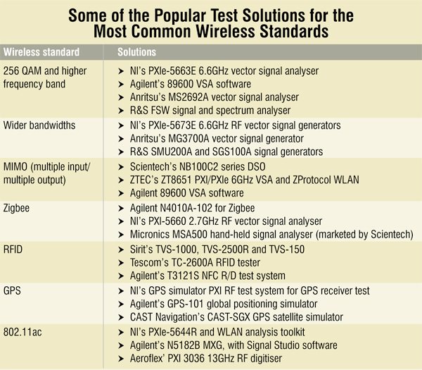
[stextbox id=”info” caption=”Some solutions for RF/wireless testing”]As with low-frequency test instruments, the world of RF test instruments is wide and varied, ranging from power meters to spectrum and network analysers and signal sources. These instruments are used to generate RF signals and measure a wide range of signal parameters.
RF power meters. Power is, without doubt, the most frequently measured RF quantity. A power meter essentially measures the power of RF signals. It uses a broadband detector and reports absolute power usually in watts and dBm.
RF spectrum analyser. Spectrum analysers are widely used to measure the frequency response, noise and distortion characteristics of all kinds of RF circuitry, by comparing the input and output spectra. These measure RF signals in the frequency domain using narrowband detection techniques. The primary output display is a spectrum of both absolute and relative power vs frequency.
RF network analyser. RF network analyser is one of the most widely used RF test equipment. It is mainly used for characterising or measuring the response of devices at RF/microwave frequencies. An RF network analyser lets you characterise an RF wave and in this way understand how it works within the RF circuit for which it is intended. It can provide both magnitude and phase information and determine transmission losses and gains of these devices over a wide frequency range with good accuracy.[/stextbox]
[stextbox id=”info” caption=”RF Nuances”]
Let’s take a look at some of the ways in which the RF domain is different and hence ends up producing some of the major challenges associated with this field. Here are some terms to help you understand the field better.
RF power. RF signal strength varies by huge amounts. As the signal travels through space, the power per unit area decreases in direct proportion to the square of the distance. Changes in power are measured in decibel (dB). dB value is a relative quantity. A related unit is dBm, which is the absolute power measured relative to 1 mW.
Mismatch on transmission lines. At low frequencies, the goal of the transmitter is to transfer voltages through circuits with minimal loss in magnitude. An ideal circuit has high input impedance and low output impedance. When dealing with RF applications where a cable length can be a quarter wavelength, signals must be treated as waves. The goal of RF is to transfer all the power to the load without loss. Any reflection of power means not all of the power is going to the load. So ‘mismatch’ is a critical parameter.
The 50Ω line. Parallel connections or multiple signal paths in RF circuits are not as simple as in low-frequency circuits. It is extremely critical to maintain a matched circuit path to minimise discontinuities and signal reflections.
RF switches are precision machined as well as designed to maintain a 50Ω impedance through the switch. To effect a parallel path, devices known as splitters or dividers separate an input signal path into two or more output paths, each with its own 50Ω impedance. Combiners perform the opposite function by converting multiple input paths into a single output path.
[/stextbox]
“Many test engineers have now realised that the old method of finding an expensive boxed instrument with the best performance numbers is now dead. Why, you may ask? The answer is simple: test engineers are getting starved of resources, mainly time, money and space. The current breed of test engineers is already using new intuitive technologies to reduce space and decrease test and development time, all in a reduced budget,” Samant adds.
The future of RF/wireless testing
The latest trends in T&M equipment for RF design include instruments with higher frequency and higher instantaneous bandwidths in a compact PCI eXtension for Instrumentation (PXI) form factor. In the next-generation wireless communication standards, we see continued trends of using more spatial streams, wider channel bandwidths and higher-order modulation types to increase data throughput. As the demand for faster data transfer rates and wider channel capacities continues to rise, precision RF components are essential to provide high-quality signals required from base-band to RF. For their exceptional accuracy and fexibility, vector network analysers have become an indispensable tool on the design bench as well as in validation test systems on the production line.
Sai Venkat Kumar B., country marcomm, Tektronix, says, “In today’s scenario, RF needs to be understood as a dynamic phenomenon. Today’s communication systems operate in burst modes and this requires the ability to understand this burst behaviour. There is also a lot of spectral reuse that can lead to interference. The real-time spectrum analyser with its real time triggers enables the user to identify these bursts of communication. In satellite domain there is a lot of malicious transmission that is hidden within a signal to disrupt signal quality. Tektronix’ real-time spectrum analyser can detect these signals, trigger on them in real time and analyse them. ”
<--nextpage-->
Using a conventional test method the system might pass all tests and work perfectly in the lab, but for a device to work in the market it needs robust testing with real-time spectrum analysers. Most of the signal generators used in the industry are very high-fidelity instruments. This makes a lot of sense if the objective is to calibrate a system. Receivers need to be tested under various stressed conditions such as multipath, distortion, quadrature error, IQ errors and interference. Most of these tests were simulated due to the lack of hardware.”
Hire explains, “With a low fixed broadband penetration of approximately nine per cent of households, mobile broadband is well-positioned to become the main means of Internet access for many Indians. This is already starting with 3G, and LTE—both TDD and FDD—will further enhance access to the Internet in the coming years.”

“In order to meet the capacity demands there will be a shift away from centrally-managed networks based on macro base stations to heterogeneous networks (HetNets) that comprise a mix of home-based femtocells, small cells (microcells and picocells) for hotspot and inbuilding coverage, and traditional macrocells. Instead of relying on centrally planned networks, with eNB parameters optimised using large volumes of drive test data, base stations will need to be designed to adapt to the RF conditions in their own environment and change dynamically,” he adds.
Chaitanya Chakravarty, application engineer, Agilent Technologies India Pvt Ltd, adds, “Recently, the demand for even higher data rates on WLAN technologies has expanded applications to wireless high definition video streaming to TV, multimedia players, video cameras, PCs, smartphones, and tablets. IEEE 802.11ac aims at a minimum 500Mbps data rate and up to around 6.93 Gbps with various enhanced technologies, including wider channel bandwidth up to 160 MHz, and higher modulation up to 256 QAM. Furthermore, MIMO plays an important role in achieving very high throughput 802.11ac with up to 8-channel beam-forming and multi-user MIMO technologies.”
Mohan Karnam, principal system architect, Posedge Technologies India Pvt Ltd, opines, “As 802.11ac chipsets became widely available, it is expected to penetrate mobile handsets. Due to power constraints on mobile handsets, these might initially support only 1×1 80MHz operation. Most aps will support at least 80MHz BW and at least three transmitter and receiver chains enabling very high throughputs. To reduce the demands for costly licensed spectrum, we will also see data off-loading by the cellular network operators to wireless LANs wherever access points are available.”
The author is a tech correspondent at EFY Bengaluru


