


MV lines are capable of transmitting power over a few kilometres, while LV lines cover only a few hundred metres. MV and LV lines are preferred for use in BPL data transmission because of their low noise level.
In order to use MV/LV lines for broadband services, BPL systems are designed to operate in the frequency spectrum range of 2 to 80 MHz. BPL signal may be injected onto power lines between two phase conductors, between a phase conductor and the neutral conductor, or on a single phase or neutral conductor. The BPL signals are injected into and extracted from MV/LV lines through inductive or capacitive couplers.
Injector is a device that aggregates user data onto the power lines and provides an interface between power line and BPL operation support system that is connected to the Internet backbone. Concentrator provides an interface between power lines carrying the BPL signal and the households.

In inductive coupling, BPL signal couples onto the line by wrapping inductors around the line. On the other hand, capacitive coupling uses a capacitor for coupling and the signal is modulated onto the line voltage. Inductive couplers are known to be rather lossy, but since they require no physical connection to the network, they are safer to install on energised lines than capacitive couplers.
Since HF signals have the rare ability to support long-distance point-to-point communications due to line noise, signal attenuation and limitations on the amount of signal power that can be injected onto power lines without causing unreasonable interference for other spectrum users, repeaters are required in between the transmission and reception ends. This can be done by using MV couplers to couple the broadband signal off the MV line so that it can be regenerated, if necessary, and amplified before being fed back onto the MV line through another coupler.
The distribution transformers that change voltage levels between MV and LV lines are particularly harsh on the weak broadband signal. These transformers, due to their high inductance, act as low-pass filters and appear as open circuits for the passage of high-frequency BPL signals. This implies that BPL signals going between MV and LV lines need to bypass the transformers. Typically, a bypass box can be used, which may consist of coupler and built-in repeating functionality.
[stextbox id=”info”]BPL can be deployed either as end-to-end BPL or as hybrid BPL. The end-to-end BPL system uses both the access BPL and the in-house BPL while in hybrid BPL, the bypass box does not couple the broadband signal to/from the LV line but converts it to/from a wireless format and delivers it to the wireless access point[/stextbox]
Connectivity to the backhaul network (Internet, PSTN, UMTS, 2G, 3G, 4G, CDMA, WiMAX, etc) is provided through the operation support system (OSS) coupled to an MV distribution line. The OSS converts data formats, aggregates and concentrates uplink data streams, provides routing functionality, helps allocate bandwidth and resources, generates billing and charging data, and provides various backhaul Ethernet interfaces to fibre-optic or wireless connections. It consists of various servers like authentication and authorisation server, dynamic host control protocol server, domain name system server and billing server to perform the required back-end tasks.
BPL can be deployed either as end-to-end BPL or as hybrid BPL. The end-to-end BPL system uses both the access BPL and the in-house BPL, i.e., power lines are used all the way from the power substation to the end user. In this case, BPL signal can either bypass the MV/LV transformer or go through the transformer (Fig. 1).
In hybrid BPL, the bypass box does not couple the broadband signal to/from the LV line but converts it to/from a wireless format and delivers it to the wireless access point (AP) located on the pole (Fig. 1).
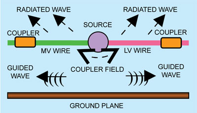 Fig. 2: BPL electromagnetic model
For end-to-end BPL, bypass boxes and LV couplers must be installed on all LV lines, and in-house BPL modems are required. For hybrid BPL, bypass boxes with wireless conversion boards, wireless APs and existing standard wireless user modems are required.
Architecture and standards
Based on seven-layer open system interconnection model defined in ISO-7498, BPL systems are designed to work on a two-layer architecture comprising physical (PHY) and medium access control (MAC) layers.
The PHY layer defines electrical and physical specifications for devices, i.e., relationship between a device and a physical medium. It includes all the electrical power line distribution system and the in-home electrical wiring down to the wall sockets. The major functions of PHY layer include establishment and termination of a connection to a communication medium, communication flow control, modulation and coding.
MAC layer, consisting of MAC lower sub-layer and logical link control layer, provides an interface between PHY layer and higher layers for connection to physical media.

Sadly due to numerous complaints by ham operators of interference, the entire BPL concept was canned and abandoned nationwide.
This is bound to happen with anything that uses RF frequencies since are no frequency bands left that aren’t already in use somewhere.
Even the coming 802.11ah wifi solution will likely be met with complaints from hams since it uses the 902-928mhz ham radio band.