


Broadcasting a high volume of information requires a very wide bandwidth, which for analogue television is five to six megahertz. For digital video broadcasting (DVB) ten times the analogue bandwidth or more is necessary. For this reason, data compression techniques are used to reduce the bandwidth so that more than one channel can be transmitted in the space allocated to a single channel for analogue TV.

There are many advantages of digital TV over analogue, such as:
1. Good picture quality
2. Increased number of channels within the same bandwidth
3. Lower transmission power
4. Reduced adjacent-channel interference
Broadcasting of digital TV signals involves digitisation, compression and channel encoding. Let’s go through digitisation and compression mechanisms in detail.
Digitisation
Digitisation is the process of converting the analogue audio and video signals into a series of bits using an analogue-to-digital converter (ADC). Digitising a TV picture means sampling the contents of the picture frame-by-frame and scan-line-by-scan-line. In order to maintain the quality of the picture, there must be at least as many samples per line as there are pixels, with each sample representing one pixel.
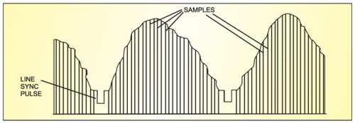
Sampling of TV signal
Sampling refers to the process of converting a continuous analogue signal into discrete digital numbers. Typically, an ADC is used to convert voltages into digital numbers. The process may be reversed through a digital-to-analogue converter (DAC).
Sampling rate. In order to convert analogue signals (which are continuous in time) into digital representation, these must be sampled at discrete intervals in time. The interval at which the signal is captured is known as the sampling rate of the converter.
If the sampling rate is fast enough, the stored sampled data points may be used to reconstruct the original signal exactly from the discrete data by interpolating the data points. Ultimately, the accuracy of the reconstructed signal is limited by the quantisation error, and is possible only if the sampling rate is higher than twice the highest frequency of the signal. This is the basis for the ‘Shannon-Nyquist Sampling Theorem.’ If the signal is not sampled at baseband, it must be sampled at greater than twice the bandwidth.
A 13.5MHz sampling rate was selected to satisfy this as well as other criteria. One is that the sampling rate must be divisible by line frequency:
13.5 = 864×15.625 for PAL
The number of active pixels per line for PAL is therefore 13.5×52 = 702
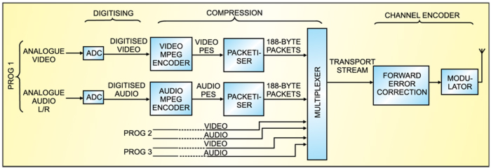
Video sampling
Colour TV broadcasting involves transmission of luminance (Y) and two colour-difference signals (R-Y and B-Y). The two colour-difference signals R-Y and B-Y are referred to as CR and CB, respectively.
In DVB, these three components are independently sampled and converted into three digital datastreams before compression, modulation and subsequent transmission. For the luminance signal, which contains the highest video frequencies, the full sampling rate of 13.5 MHz is used. As for chrominance components CR and CB, which contain lower video frequencies, sampling rate of 6.75 MHz is used. It is followed by the multiplexer, where all the three streams are combined into a single stream and a total sampling rate of 13.5 + 6.75 + 6.75 = 27 MHz is obtained.
Sampling structure. During the digitising process, the three parameters of the component video signal are assigned a numeric sampling value. Groups of four video pixels within each of the three components are looked at and samples taken for recording. With a 4:2:2 sampled video signal, all four of the luminance pixels, two R-Y pixels and two B-Y pixels are sampled. This gives a 4:2:2 sampling rate.
With a 4:1:1 signal, all four of the luminance pixels are sampled four times but only one pixel is sampled from each of the R-Y and B-Y. This lower sampling rate of the colour components results in less colour information being recorded, affecting the accuracy and intensity of the colour in the video signal.
4:1:1 may not be used when doing chroma-keying, graphics and other compositing functions, as all of these functions require strong colours to be present in the video signal. The advantage of 4:1:1 sampling is that you can record twice as much information as 4:2:2 on the same area of video tape, thus providing twice as much recording/playback time within a given tape length. And, of course, the circuitry within the equipment is less expensive for a manufacturer to produce.