In the quest to control lightning, the laser lightning rod (LLR) project aims to explore the use of a laser-based technique to stimulate upward lightning discharges initiated through a high repetition rate multi-terawatt laser.
In Norse mythology, Thor, the god of thunder, wields a mighty hammer capable of controlling lightning. Inspired by this legend, scientists are exploring a futuristic solution to the age-old problem of lightning strikes. Current methods, like Benjamin Franklin’s lightning rods, offer localised protection but fall short for larger structures such as airports for wind farms.

Enter the laser, a high-tech alternative poised to revolutionise lightning defence. By emitting quick energy pulses, lasers can create a conductive path through the air, guiding lightning safely to the ground. This innovative approach promises to safeguard lives and property on a grand scale, offering flexibility and precision unmatched by traditional methods. With the power of science and the spirit of ancient myth, humanity may soon tame the thunderbolts that once wreaked havoc from above.
What is a laser
A laser is a device that stimulates atoms or molecules to emit light at particular wavelengths and amplifies that light, typically producing a very narrow beam of radiation. Laser is an acronym for ‘light amplification by the stimulated emission of radiation’.
A simplified diagram of a ruby crystal laser has been shown in Fig 2. The device consists of the following components:-

- A high-voltage electric supply makes the xenon tube (item 2) flash on and off.
- Every time the tube flashes, it ‘pumps’ energy into the ruby crystal (item 5). The flashes it makes inject energy into the crystal in the form of photons.
- Atoms in the ruby crystal (large green circles) soak up this energy in a process called absorption. Atoms absorb energy which causes their electrons to jump to a higher energy level. After a few milliseconds, the electrons return to their original energy level (ground state) by giving off a photon of light (small blue blobs). This is called ‘spontaneous emission’’.
- The photons that atoms give off jump up and down inside the ruby crystal, travelling at the speed of light.
- So, often, one of these photons stimulates an already excited atom, and when this happens, the excited atom gives off a photon and the original photon is also given back. This is called ‘stimulated emission’.Now, one photon of light has produced two. This means light has been amplified by stimulated emission of radiation.
- A mirror (item 6) at one end of the laser tube keeps the photon bouncing back and forth inside the crystal.
- A partial mirror (item7) at the other end of the tube bounces some photons back into the crystal, butlets some escape.
- The escaping photons form a very concentrated beam of coherent, powerful laser light (arrow 8).

Lightning research at the santis observation
Since the first laser was invented in the 1960s, researchers have considered utilising them to guide lightning. Theoretically, a laser beam would create a straight path of ionised air through which current could flow while facing less resistance. But, in practice, it was found that high- powered lasers failed to perform because, within a short distance, the ionised air absorbed the laser light, leaving the air channel not conductive enough to attract lightning. In the 1990s, researchers developed lasers that produced pulses just femtosecond long. These shorter, lower energy pulses proved more effective at opening conductive channels. This laser light ionises some air, which then works as a lens to further focus the light into a long ‘filament’ the width of a hair. The thin beam heats the air, driving away molecules and leaving a lower-density channel , providing better conditions for electric current flow.
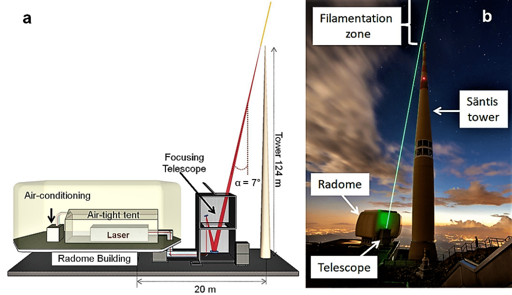
At the top of Santis Mountain, Switzerland, at an altitude of 2481m, there is a 123m tall radio/TV transmitting station equipped with a conventional lightning rod, which also has been used for lightning research purposes. Researchers installed a laser-assisted lightning rod (LLR) at the very summit of Mount Santis and operated it in conjunction with the standard lightning rod. The LLR (1.5m wide X 8m long) weighs more than three tons.
Scientists found that if a laser is used, the lightning discharge could follow the laser beam for nearly 60m before reaching the tower, increasing the protection of radius from 123m to 183m. This is a significant jump. The researchers want to increase the laser’s capabilities by extending its reach and protection zone. With this success as proof of concept, lasers could one day protect large infrastructures like airports, launch pads, big industrial complexes, etc., from lightning strikes.
Laser system
During the experimental campaign at Santis Mountain, it was found that the most suitable system was the Yb: YAG chirped pulse amplification (CPA) laser system developed by TRUMPF Scientific Lasers. It can deliver laser pulses at 1030nm with 720mj of energy per pulse and a pulse duration of 920fs at arepetition rate of 1kHz. However, for the laser set-up, which features a long propagation before reaching the transmitting telescope, it is necessary that the output energy is reduced to 500mj and the pulse is chirped to a pulse duration of 7ps to prevent damage to the optics.
Chirped pulse amplification
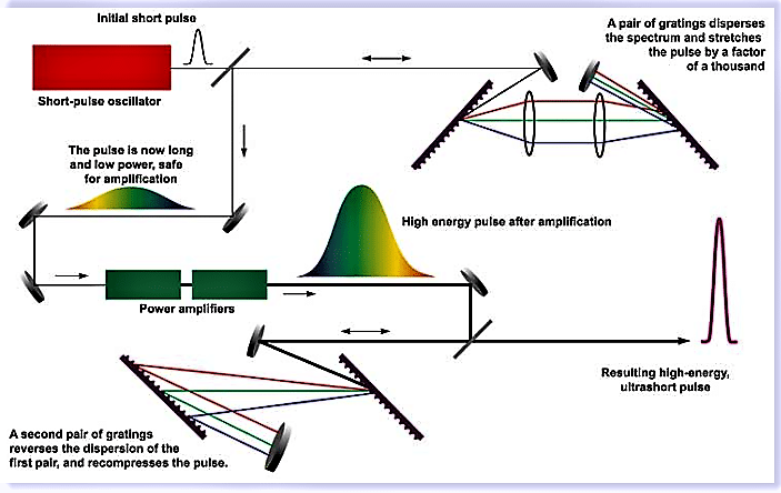
Chirped pulse amplification (CPA) is a technique for amplifying an ultrashort laser pulse up to petawatt level, with the laser pulse being stretched out temporarily and spectrally, then amplified, and then compressed again, as shown in Fig 3. The stretching and compression uses devices that ensure that the different colours of the pulses travel different distances. Before the invention of CPA, the peak power of laser pulses was limited because a laser pulse at intensities of gigawatts per sq. cm, if allowed to propagate in the air or the laser gain medium, would instantly self -focus and form a plasma and damage the laser components.
In CPA, an ultrashort laser pulse is stretched out in time before introducing to the gain medium using a pair of gratings arranged so that the low-frequency component of the laser pulse travels a shorter path than the high-frequency component. After going through the grating pair, the laser pulse becomes positively chirped, meaning the high-frequency component lags behind the low-frequency component, and has a longer pulse duration than the original by a factor of 103 or more. Then, the stretched pulse, whose intensity is now sufficiently low, can be safely fed to the gain medium and amplified by a factor of 106 or more.
Finally, the amplified laser pulse is recompressed back to the original pulse width through the reversal process of stretching, achieving higher peak power(2). A compact table top terawatt laser can be made using this technique. The gratings are made of monolithic fused silica with a high laser-induced damage threshold, or it can be made of metal. A simplified diagram of CPA laser is shown in Fig – 3.
Laser system used in LLR
A schematic diagram of the CPA laser system used in the laser lightning rod is shown in Fig 4. For a long time, researchers have been using the Ti: Sa lasers. However, the average power these lasers provide is limited to a few watts and the 30% quantum defect of Ti: Sa system induces a significant heat load. Yb-doped laser crystals have a lot of advantages. They are now preferred for fabricating of high-powered lasers, providing kilowatts of optical power at the main absorption band of 940nm. It has a low quantum defect of about 9%, generating deficient heat. Moreover, their long fluorescence lifetime of about 0.9ms and excellent thermal conductivity allow continuous wave pumping and operation at very high power levels.
Thin disc geometry
The thin disk geometry has made these lasers suitable for high-power scaling, providing multi-kilowatt laser output power. Heat dissipation is a major challenge in conventional lasers using a laser rod as an active material. Cooling the rod via its surface is rather inefficient due to the large volume to surface ratio.
Additionally, it generates a temperature gradient perpendicular to the laser axis, which results in thermal lensing. Using a thin disk cooled from one side is the logical step towards better cooling and, consequently, higher output power. The main advantage of the thin disk is that it can be cooled very efficiently by contacting its surface with diamond or copper heat sinks, minimising thermal lensing and thermally-induced wavefront aberrations. From a single disk, up to 4kW in the fundamental mode and up to 16kW can be achieved with an optical efficiency as high as 70%. The cooled end face has a dielectric coating, reflecting both the laser and pump radiation. The thin disk also acts as a mirror with double laser gain per round trip, and the threshold pump power is thus reduced. The small thickness of the disk leads to inefficient pump absorption when only a single or double pass is used. This problem can be solved by using a multi-pass arrangement. Fig 5 shows a schematic set-up of a thin disc laser head.

The multipass pump arrangement can be made fairly compact, typically containing a parabolic mirror and prism retro-reflectors. Such arrangements can accommodate 8 or 16 double passes of the pump radiation easily. Compared with high-power fibre lasers, thin disc lasers require less brightness of the pump diodes. The pump source of these lasers is generally provided by high-power diode bars. A typical pump wavelength is 940nm for Yb: YAG. Due to the small thickness of the disk, e.g., 100-200µm for Yb: YAG, the temperature rise is slight . The scaling property of a thin disk is simple. The output power can be doubled by increasing the pump power twice to twice the area on the disk while keeping the disk thickness and doping level constant. In multimode operation, 16kW using disks in one resonator is commercially available.
Regenerative and multi pass filter
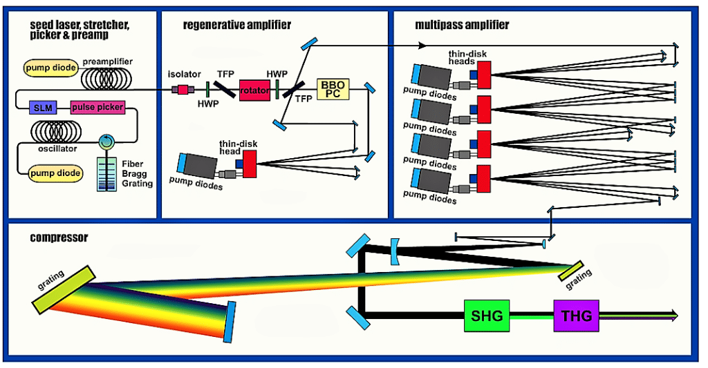
A high-powered CPA laser system generally uses a seed laser as the starting point, as shown in Fig 4. Typical seed lasers are small laser diodes, short-cavity fibre lasers, and miniature solid-state lasers. Instead of a single high-powered laser, using a low-powered seed laser is convenient for obtaining features like single frequency operation with narrow bandwidth, a wide wavelength tuning range, or the generation of ultrashort pulses. A seed laser combined with a preamplifier forms a master oscillator power amplifier configuration for generating high-power output. The low-powered laser pulses from the seed laser preamplifier are sent to regenerative/multipass amplifiers to boost their power. The principle of operation of a regenerative amplifier is given below:
a) The gain medium is first pumped for some time so that the system stores some energy.
b) The input light pulse is injected into the resonator through a port, which is opened briefly with an electro-optic switch. A Pockels cell, combined with a quarter-wave plate and a thin-film polariser (TFP), acts as an optical switch. An optical isolator or diode, shown in Fig 4, is an optical component that allows light transmission in one direction only. It typically prevents unwanted feedback into an optical oscillator like a laser cavity. The main component of the optical isolator is the rotator. The magnetic field applied to the rotator causes a rotation in the polarisation of light due to the Faraday effect. If some linearly polarised beam is sent through the rotator and back again after reflection at a mirror, the polarisation changes of the two passes add up rather than cancelling each other.
c) Next, the pulse can undergo many hundreds of resonator round trips and beamplified to a high energy level.
d) Finally, the amplified pulse in the millijoule range, with a repetition rate of 1kHz or more, is released from the resonator with the help of a second electro-optic switch.
A regenerative amplifier provides a high gain, and when combined with a multipass amplifier, the latter boosts the energy. In a multipass amplifier, multiple passes are arranged with a set of mirrors,and each pass has a slightly different propagation direction each time. Both approaches must be combined to achieve high gain and boost energy(4).
Broad working philosophy of CPA laser of LLR
The schematic arrangement of the LLR laser system is shown in Fig 4. Ultrashort seed pulses are produced by an industrial fibre-based ultrafast laser stretched by a chirped fibre. Bragg grating ispreamplified in an active fibre. The preamplified pulses are fed to a Dira 200-1 TRUMPF Scientific regenerative amplifier with a thin disc laser head, the first high-power amplifier stage, delivering 200mj output pulse energy. In the second stage, the 200mj energy is further amplified to a 1-joule level before pulse compression in another four thin- disk laser heads arranged in a multipass configuration. Each thin-disk laser head can be pumped with 10kW of optical power. This way, a signal can be amplified to pulse energy up to the joule level, continually operating below the laser-induced threshold level.
Finally, pulse compression is achieved by double passing a grating compressor with a pulse duration below 1ps. At 1kHz repetition rate, the average output power before compression reaches around 800W, translating to 800mj. After recompression, the pulse energy remains at 720mj due to loss in diffraction. Besides the fundamental wavelength of 1030nm, the second and third harmonics at 515nm and 343nm are also provided via SHG and THG conversion stages after the compressor. *
Experimental campaign
Lightning has fascinated and terrified humanity since it was immortal. It is estimated that about 120 flashes per second worldwide cause considerable damage. Therefore, providing a better protection system against this natural phenomenon is essential.
A continuously operating technique to trigger and guide natural lightning is highly desirable. The first test was performed in the 1970s using long lasers of pulses of several nanoseconds was not very effective. This approach was forsaken, as the plasma generated with such a long IR pulse had a discontinuous profile due to electron avalanche, and a huge laser energy was required to extend the laser-generated plasma column beyond a few metres. It is found that a sub-100fs laser pulses are short enough to arrest electron avalanche. The generated plasma remains transparent to the laser pulse; hence, ionising self-guided filaments can exceed 100m in length.
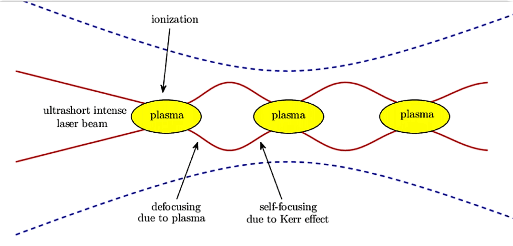
Filamentation is the ability of a very intense ultrashort laser pulse to remain focused over an extended distance. Laser-induced filamentation is a nonlinear optical effect where intense laser pulses undergo self-focusing from the Kerr effect to overcome pulse diffraction and propagate distances much larger than the diffraction length while maintaining a narrow beam diameter, as shown in Fig 6. A terawatt laser of 100mj, 1030nm,1kHz repetition rate can reduce the breakdown voltage by 3, forming a permanent low-density channel capable of guiding lightning discharges over a long distance. Along these filamentary regions, the air is rapidly heated by the absorbed laser energy and expelled at supersonic speed, leaving long-lived air channels with reduced density. These low-density channels of millisecond lifetime have higher electronic conductivity and provide a low resistance path of electrical discharges. The filamentation process can be remotely controlled to initiate the filamentation process a km away from the laser source and trigger lightning discharges safely to earthing.
In 2021, Laser Company Trumpf and the University of Geneva fired up a laser- based lightning rod at the top of Santis Mountain in Switzerland. They control lightning from storm clouds and direct the strikes to places where they won’t cause any damage. As shown in Fig 7, to comply with the environmental requirements, the laser is located at a random 20m away from the tower, sheltered in an airconditioned air-tight polyester tent where the temperature is maintained around 200C and 50% relative humidity. The laser output beam is directed through the random skin through a 200mm diameter metal tube, leading the beam into an isolated aluminium housing, where a 100mm folding mirror directs the beam into a beam-expanding transmitting telescope with a magnification of 7.14. The final beam diameter is 250mm, focusing close to the tower tip. The telescope is designed so the beam exit matches the 70 angle to reach the tower top. The filament onset distance is tuned by controlling focusing.
How the system works
The laser blasts short, intense bursts of infrared light at the clouds about 1000 times per second. Each pulse carries roughly a terawatt, which means one million watts of instantaneous energy. This energy can only be delivered for a very tiny amount of time, about a picosecond. The pulse is a travelling line segment. This is a nonlinear optical process. Power density in the pulse increases as the pulse shrinks, enhancing the effect and creating a feedback loop. The laser pulse undergoes self -focusing. The air acts like an increasingly vital lens, cramming the laser power into a more intense pulse. This continues until the air is ionised, i.e., air and its electrons are separated, forming plasma. Next, freed electrons in the plasma counteract the focussing. For a brief period, the self-focusing of the laser and the de-focusing of the electrons balance, forming a plasma filament along the pulse path. Eventually, the pulse’s energy is dissipated, and the self-focusing process falls off, closing the filament tube. The filament tube formed in this campaign was about 50m long, and most lightning channels were kilometres long. Scaling the laser system to have a useful reach may take a lot of work. It is felt that by increasing the laser power and adjusting its other parameters, the length of the filament would simply improve. Along the length of the filament thus formed, as explained earlier, the air molecules hit by the pulse are stripped of electrons and then blasted out into the surrounding atmosphere. The filament collapses for a nanosecond but leaves behind a tube of altered air that lingers for a millisecond. Within the tube, a combination of lower density of air and higher density of electrons provides an attractive low resistance pathway for lightning strikes to travel to a safer zone, as shown in Fig 8.
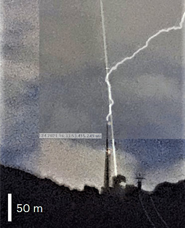
Over two months, the researchers operated their lasers for 6 hours, during which several lightning strikes struck the tower. High-speed photography and radio emissions from lightning discharges confirmed that laser-induced filaments successfully guided 4 out of 4 lightning strikes while the system was active. These strikes were aligned with the laser path. As shown in Fig 9, harmful lightning strikes can be conveniently diverted with the help of the LLR to a secure location where a conventional lightning rod is installed, and the powerful lightning, instead of striking the vital installation like a rocket launching pad, would be safely discharged to the ground.
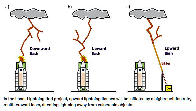
The laser lightning rod (LLR) emerges as a promising technology, with successful experiments redirecting lightning’s path. The next phase aims to demonstrate the technology’s capacity to trigger lightning, ensuring protection for critical infrastructure worldwide.