


How to drive a power LED?
LEDs require a constant-current source, rather than constant-voltage. For the winky-blinky and lower-power types, a resistor does the trick. For LEDs above 1W, the resistor becomes impractical. Standard switch-mode power supply (SMPS) topologies and controllers can be used to drive the LEDs at these high power levels, using LED current instead of voltage as the feedback to the controller. The choice of topology depends on the system input voltage, LED forward voltage and the number of LEDs connected in series.
Clean power
So far we have discussed only the power-conversion circuits that allow an LED or fluorescent tube to be driven from a DC bus. How current is drawn from the AC line is of equal importance. Typically, a bridge rectifier circuit with filter capacitors consumes current from the AC line only at the peaks of the AC input voltage. The result is a current waveform with a high harmonic content and poor power factor.
An active PFC circuit can improve conversion of AC power into DC power. In simple terms, an active PFC circuit forces the current consumption of the circuit to track the envelope of the incoming AC line voltage. PFC helps to meet energy-efficiency requirements. Thus it helps customers achieve a faster payback for electronic lighting controls.

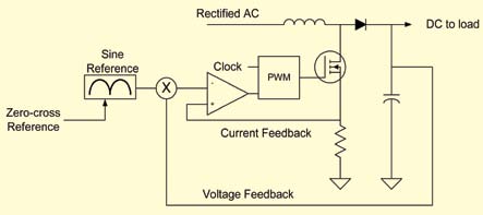
Active PFC is most easily implemented using a voltage-boost circuit with an outer voltage-feedback loop and an inner current-control loop. The voltage-feedback control loop provides the demand for the inner current-control loop and determines whether more or less current is required to achieve the desired bus voltage. The current loop demand is then used to scale a sinusoidal reference signal.
The sinusoidal reference signal can be derived in two ways. First, it can be measured directly from the rectified AC input voltage. A simpler solution uses a sinusoidal reference stored in the memory of the MCU. A PWM channel on the MCU can be used as a simple digital-to-analogue converter to generate the sinusoidal reference. An R-C filter is connected to the PWM output pin to convert the PWM signal into a voltage.
The values in the sinusoidal table are scaled up or down by the current demand from the voltage control loop. The sinusoidal reference signal stored in the memory is synchronised to the zero crossings of the incoming AC voltage, using an interrupt on the MCU.
The use of a sinusoidal reference table assumes that the incoming AC voltage is purely sinusoidal and does not have any distortion. This assumption is practical for many applications. Consequently, the method is known as indirect PFC. Fig. 7 shows the block diagram of indirect PFC.
Communication control and status
MCUs allow communication to be integrated into lighting applications. This is especially important for commercial applications where regulations and energy pricing incentives may dictate the use of daylight harvesting, occupancy sensors and other automatic control methods.
The most common method for dimming in large installations is analogue 0-10V DC control. It can be incorporated into the design using an analogue-to-digital converter (ADC) channel.
More sophisticated digital communication solutions, such as digital addressable lighting interface (DALI) and DMX-512, rely on an MCU-based design. DALI is a bidirectional protocol for controlling multiple light fixtures on a two-wire bus. It uses a 1200-baud, bi-phase signal that is easily generated by an MCU. The protocol can address one of 64 lighting fixtures individually (or one of 16 groups, as 16 individual groups can be formed out of the 64 addresses) or broadcast to an entire network. Advanced features such as fading, logarithmic profiles and scene control can be implemented. Since the protocol is bidirectional, fault information can be sent to a host controller.
As the name implies, DMX-512 allows dimming signals for 512 lighting channels to be multiplexed onto one wire. The protocol evolved from analogue multiplexing protocols used in theatre and entertainment industries. DMX-512 can be implemented with a standard UART operating at 250 kilobauds and uses an RS-485 differential driver to allow transmission over long distances.
One disadvantage of DMX-512 is that it provides only unidirectional communication. A new extension to DMX-512, called remote device management (RDM), has recently been proposed as a means to offer bidirectional communication. RDM would also allow remote setting of the node addresses.
One of the disadvantages of DALI, 0-10V and other control schemes is that separate wiring needs to be run to each fixture. With an MCU, control schemes are possible that eliminate the extra wiring. Some systems use the chopped AC waveforms, generated by a TRIAC dimmer as a dimming signal for the ballast. It is also possible to use power-line modem communication schemes. Infrared communication could be used to control multiple fixtures in the same space.
One emerging wireless protocol, called ZigBee, provides a cost-effective solution for low-data-rate control networks and could have potential for use in lighting-control applications. The protocol provides self-commissioning of network nodes and security features.
LED driver issues
The use of MCUs in LED driver applications facilitates PWM dimming. The easiest way to dim a LED is to adjust the current output level of the switch-mode or linear driver.
However, linear dimming is not preferred for two reasons. First, the LED doesn’t operate at its optimal efficiency point over the brightness range. Second, linear dimming can produce a colour shift in the light output of the LED.
PWM dimming solves both of these issues by modulating the LED output with a low-frequency PWM signal. The LED is turned on at a single current-drive level. Its brightness is adjusted by changing the average time period for which the LED is active.
PWM control and LED drive functions can be integrated into a single-chip solution. Or, a low-cost MCU with as few as six pins can be used to generate the PWM dimming signals for a separate driver circuit.
Fluorescent ballast issues
As shown earlier, the fluorescent bulb can be dimmed using a precise, variable-frequency source. The drive-current level is reduced by moving the drive frequency away from the resonant frequency of the L-C circuit. The dimming performance of the electronic fluorescent ballast can be improved further by monitoring the bulb current with the MCU. This allows the bulb current to be set at exactly the right level for the desired output. Furthermore, the MCU can determine whether the lamp has failed to start.
For ballast manufacturers, an MCU-based solution permits a flexible platform. The MCU can easily be reprogrammed with different startup profiles for different types of bulbs and different L-C circuit values.
Why use an MCU?
At first, you might not consider the use of an MCU for a lighting application. However, MCUs can be integrated into the design at any level to create efficient lighting applications. These can handle both communication and power-control functions. Furthermore, they provide a flexible platform that can be easily programmed to create new features and functions.
The author is a technical staff engineer at Microchip Technology Inc.
