A capacitor by structure consists of two conductors separated by an insulator that is often referred to as a dielectric. It is often used to filter out DC component in electronics circuits as it only allows DC component to pass through. Meaning, for very low frequencies (high DC component low AC component), the capacitor acts as an open circuit. Inversely for high frequencies (high AC component, low DC component), it acts a closed circuit. This phenomenon is better by capacitive reactance.
Calculating capacitive reactance
The lower the frequency of the applied voltage, the more time capacitor takes to be charged fully, before the voltage reverses its polarity and begins to discharge the capacitor again. The capacitor therefore spends more time fully charged and passing much less current, resulting in less current flow at low frequencies. When a higher frequency is applied, the capacitor changes from charging to discharging faster allowing more current to flow. The opposition to current flow in any capacitor is inversely proportional to the frequency and is represented by the formula:
![]()
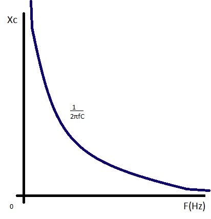
Capacitive reactance graph

Capacitive reactance (symbol XC) is a measure of a capacitor’s opposition to AC (alternating current). Like resistance it is measured in ohms, but reactance is more complex than resistance because its value depends on the frequency (f) of the signal passing through the capacitor. Reactance is also inversely proportional to the value of capacitance (C), i.e. the value of XC at any frequency will be less in larger capacitors than in smaller ones. All capacitors have infinitely high values of reactance at 0Hz, but in large capacitors, the reactance falls to a low level at much lower frequencies than in smaller capacitors. Hence, larger capacitors are preferred in low frequency applications.
Feel interested? Check out other electroncis basic articles in the learning corner.


