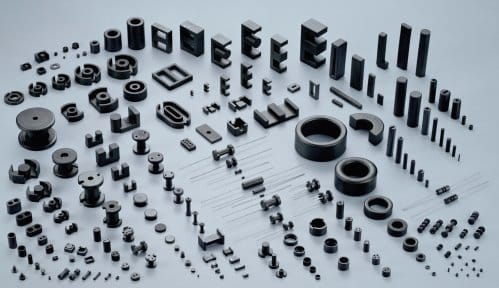
A ferrite transformer has a magnetic core in which coil (inductor) windings are made on a ferrite core component. It offers low eddy current losses. It is normally used for high-frequency applications. Common ferrite core types are toroidal, closed-core, shell and cylindrical.
Depending on circuit designs, core types and applications of transformers, there are different topologies and names. These include shell type, pushpull, half-bridge and flyback. Irrespective of the topologies, some points to be kept in mind while designing ferrite transformers include frequency and temperature of operation, unit cost, size and shape. These should match the voltage levels of source and load, provide electrical isolation, prevent core saturation and minimise core losses.
The size and frequency of operation of a ferrite transformer depends on two broad applications: signal and power. A ferrite transformer used in signal applications is small and has higher frequencies (in the range of mega-Hertz). The one used in power applications is large and has lower frequencies (normally ranging from 1kHz to 200kHz).
Steps for designing a ferrite transformer
Application
Before designing a transformer, check your requirement and exact application. This may include input voltage, output voltage, current and frequency of operation. Then, consider other parameters like physical size, spacing, mounting style, isolation, leakage currents and temperature.


Core selection
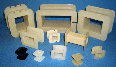
Most core types need bobbins to fit the cores you choose, and assist in the mounting of the finished product. Make sure the bobbin style and materials are available in the local market. Then, calculate the correct number of turns, power losses and other parameters. You may refer to the formulae given on the following websites:
Winding
Primary winding current and wire size need to be determined. Primary current is equal to total output power plus transformer power losses, divided by primary voltage.
Next comes the number of turns needed for secondary winding. For this, check if the wires fit into your winding area in the bobbin, height and mean length of turns from the mechanical drawing.
Include insulation used between windings, while considering total winding height.
Verification
Verify the design by measuring open-circuit and loaded voltages across secondary winding. For this, calculate resistance of each winding. Then, calculate voltage drop across that winding by multiplying resistance and current in the winding.
Calculate open-circuit voltage and loaded voltage across secondary winding using the formulae given in the above-mentioned websites.
Temperature calculation
Acceptable temperature rise depends on the application and the designer. Two main causes of temperature rise in a transformer are core power losses and winding power losses. These can be calculated using standard formulae.


Good article. Greetings to you. I have many ferrite core from TRC TV flyback Transformers and I would like to know if I can build a DC – DC (12V to +/-35V ) power supply to feed small amplifiers. I want to make use of these cores because sometimes I wish to get rid of them but I think they would be useful for me for some applications. Thank you for your answer.
Thanks for the feedback! This kind of TV flyback transformers are meant for high voltage and high frequency applications. However, if you have spare ferrite cores and space is not an issue, you can use them but I think it would be a bit bulky.