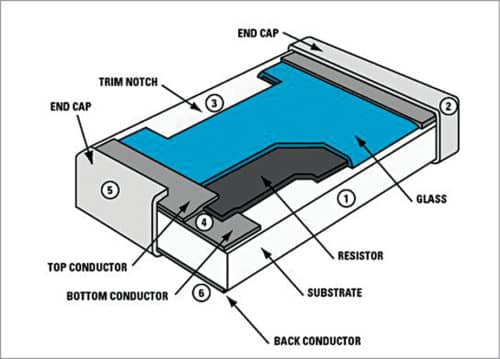
Chip resistors are also known as surface-mount devices or SMD resistors. Chip resistors are manufactured using metal oxides or metal films, and are protected using robust coatings. These are small and mostly available in square or rectangular chip packages.
Unlike through-hole-technology (THT) resistor devices, SMD resistors do not have leads. These are mounted directly onto the PCB. SMD resistors are manufactured in a precise way in automated facilities, and these have superior heat dissipation characteristics and stable resistance values. The length and width of SMD devices determine their power ratings.
SMD resistor code
Because of the small size of SMD resistors, there is no room for traditional colour band codes to be printed on them. Therefore new resistor SMD codes have been developed. The most commonly-used codes are three-digit and four-digit systems, and an Electronic Industries Alliance (EIA) system called EIA-96. The most widely-used general SMD resistors are made in various sizes, ranging from 0402 to 6432.

Three-digit code
These are three-digit codes where the first two figures indicate significant figures and the third is a multiplier. This is the same as the coloured rings used for normal resistors, except that numbers are used instead of colours. For example, an SMD resistor with 562 has a resistance of 56×102 ohms, or 5.6kΩ. Similarly, an SMD resistor marked with 100 means it is 10×100 or 10×1=10Ω.
Four-digit code
The four-digit marking scheme is used for marking high-tolerance SMD resistors. Four digits implies one per cent or less tolerance. Its format is similar to the three-digit marking scheme. The first three numbers indicate significant digits and the fourth is the multiplier. For example, an SMD resistor with 4702 means 470×102 ohms, or 47kΩ.
SMD resistors can have a fixed value of resistance, or these may be variable or adjustable within a certain range. It is simpler to substitute the potentiometer with a trimmable chip resistor.
Trimmable resistors
These are also SMD resistors, but the trimmable resistors can be trimmed into a wide range of resistive values. Resistance values depend on length, width, height and material. Lasers are used to burn some portion of the resistors to trim them. These resistors are intended to be used in all applications requiring an initial calibration. These can be used as substitutes for trimming potentiometers or manually-selected fixed resistors to calibrate them in an electronic circuit.
Benefits include cost reductions, space savings and the full, automatic in-line trimming process with reduced tuning time.


