An “ideal” or perfect operational amplifier is a device with certain special characteristics such as infinite open-loop gain, infinite input resistance, zero output resistance, infinite bandwidth, and zero offset.
Operational amplifiers are used extensively in signal conditioning or perform mathematical operations as they are nearly ideal for DC amplification. It is fundamentally a voltage amplifying device used with external feedback components such as resistors and capacitors between its output and input terminals.
An operational amplifier is basically a three-terminal device consisting of two high impedance inputs, one called the inverting input (–) and the other one called the non-inverting input (+). The third terminal represents the operational amplifiers output port which can both sink and source either a voltage or a current.
Negative Feedback
While on the one hand, operational amplifiers offer very high gain, it makes the amplifier unstable & hard to control. Some of this gain can be lost by connecting a resistor across the amplifier from the output terminal back to the inverting input terminal to control the final gain of the amplifier. This is commonly known as negative feedback and produces a more stable op-amp.
Negative feedback is the process of feeding a part of the output signal back to the input. But to make the feedback negative, it is fed to the negative or “inverting input” terminal of the op-amp using a resistor. This effect produces a closed loop circuit resulting in Closed-loop Gain. A closed-loop inverting amplifier uses negative feedback to accurately control the overall gain of the amplifier, but causes a reduction in the amplifiers gain.
Inverting Amplifier
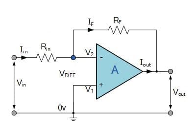
In an inverting amplifier circuit, the operational amplifier inverting input receives feedback from the output of the amplifier. Assuming the op-amp is ideal and applying the concept of virtual short at the input terminals of op-amp, the voltage at the inverting terminal is equal to non-inverting terminal.
The non-inverting input of the operational amplifier is connected to ground. As the gain of the op-amp itself is very high and the output from the amplifier is a matter of only a few volts, this means that the difference between the two input terminals is exceedingly small and can be ignored. As the non-inverting input of the operational amplifier is held at ground potential, this means that the inverting input must be virtually at earth potential.
Applying KCL at inverting node we can calculate voltage gain,
Voltage gain (A)= Vout/ Vin = – Rf/Rin
Non-Inverting Amplifier
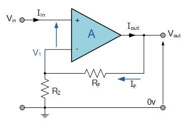
The non-inverting amplifier is one in which the output is in phase with respect to the input. The feedback is applied at the inverting input. However, the input is now applied at the non-inverting input. The output is a non-Inverted (in terms of phase) amplified version of input.
The gain of the non-inverting amplifier circuit for the operational amplifier is easy to determine. The calculation hinges around the fact that the voltage at both inputs is the same. This arises from the fact that the gain of the amplifier is exceedingly high.
If the output of the circuit remains within the supply rails of the amplifier, then the output voltage divided by the gain means that there is virtually no difference between the two inputs.
The voltage gain can be calculated by applying KCL at the inverting node.
Voltage gain (A) = Vout/ Vin = (1+ Rf/Rin)
FAQs
What is the difference between an inverting and a non-inverting amplifier?
An inverting amplifier produces an output that is inverted and amplified relative to the input signal, while a non-inverting amplifier produces an output that is amplified but not inverted.
What is the gain of an inverting amplifier?
The gain of an inverting amplifier is determined by the ratio of the feedback resistor to the input resistor.
What is the gain of a non-inverting amplifier?
The gain of a non-inverting amplifier is determined by the ratio of the feedback resistor to the input resistor plus one.
What are the applications of inverting amplifiers?
Inverting amplifiers are commonly used in audio and instrumentation circuits where the signal needs to be amplified and inverted.
What are the applications of non-inverting amplifiers?
Non-inverting amplifiers are commonly used in voltage follower circuits, as well as in audio and instrumentation circuits where the signal needs to be amplified without being inverted.
What is the input impedance of an inverting amplifier?
The input impedance of an inverting amplifier is equal to the input resistor.
What is the input impedance of a non-inverting amplifier?
The input impedance of a non-inverting amplifier is very high, typically in the megaohm range.
What is the output impedance of an inverting amplifier?
The output impedance of an inverting amplifier is very low, typically in the ohm range.
What is the output impedance of a non-inverting amplifier?
The output impedance of a non-inverting amplifier is typically the same as the input impedance.
Which amplifier configuration is more commonly used in audio amplifiers?
Non-inverting amplifiers are more commonly used in audio amplifiers because they do not invert the signal and maintain the phase integrity of the audio signal.
This article was first written on 7 November 2017 and was updated on 4 April 2019.


Hi Sir very nice work and truly information given about of all Digital item also related to op-amp .
Thank you
Thank you for your feedback.
Great writeup! One point of correction:
In the Non-Inverting topic, the formula is written as Voltage gain (A) = Vout/ Vin = (1+ Rf/Rin)
The Diagram above shows R2 not Rin…. This may confuse some readers.
Thank You Nick, we will review and correct the article as soon as possible.
Hi,
Why do these inverting and non-inverting amplifiers use different configurations? I would think that just switching the opamp inputs in the non-inverting amplifier turns it into an inverting one (with a gain of -(1+Rf/Rin) and exchanging the inputs in the inverting amplifier would make it a non-inverting one (with a gain of Rf/Rin).
Can you explain where did you put R input in non inverting amplifier diagram
I want to Dc tranfermer low volt high volt 3 face Ac OF ON Relay Diagram.