Light Dependent Resistors (LDRs) are essential components in various electronic applications, relying on the principle of photoconductivity to function. This article delves into the construction and working principles of LDRs, alongside a look at their circuit implementation.
Construction of a Light Dependent Resistor
The construction of Light Dependent Resistors (LDRs) is a precise process designed to optimize both functionality and environmental safety. The key component of an LDR is a photosensitive material, which is applied to an insulating substrate, often made of ceramic. This substrate forms the foundational layer upon which the LDR operates.

Materials and Design:
The foundation of an LDR construction involves applying a photosensitive material onto an insulating substrate, typically made of ceramic. This material is most commonly cadmium sulphide (CdS), known for its effective photoconductive properties. It is arranged in a zigzag pattern across the ceramic substrate to maximize the reactive surface area, which is critical for enhancing the light-absorbing efficiency of the LDR. This pattern not only optimizes light absorption but also creates distinct zones within the device, each contributing to the desired electrical resistance and power handling characteristics.
Metal Contacts and Assembly:
To integrate the photosensitive material into a functional circuit, metal films are strategically placed at each end of the ceramic base. These are known as Ohmic contacts and are crucial for establishing a reliable electrical connection with minimal resistance. The placement and quality of these contacts are meticulously controlled to ensure that any change in the LDR’s resistance is primarily due to the photoconductivity response to light, rather than imperfections or variability in the contact points.
Environmental Considerations:
In modern LDR designs, the selection of materials takes into account environmental impact. Harmful substances like lead and cadmium, traditionally used in the manufacture of photoconductive materials, are increasingly being phased out. This shift reflects a broader commitment within the electronics industry to reduce ecological footprints and improve the sustainability of electronic components.

Housing and Protection:
Once assembled, the LDR is encased in a clear plastic or resin housing. This casing is crucial as it protects the delicate internal components from physical damage and environmental contaminants, while also allowing light to reach the photosensitive material without obstruction. This transparent enclosure ensures that the LDR can perform its light-sensing function effectively, responding to environmental light changes with high sensitivity and reliability.
The meticulous construction process of LDRs, from the choice of substrate and photosensitive materials to the environmental considerations and protective casing, illustrates the sophisticated integration of materials science and engineering to create devices that are both sensitive to light and durable in structure.
Also Read: different types of LDRs
Working Principle of LDR
The functionality of Light Dependent Resistors (LDRs) is governed by the phenomenon of photoconductivity, an optical effect where the conductivity of a material increases with light absorption. This section delves into how LDRs use this principle to respond to changes in light conditions, making them invaluable in various light-sensing applications.
Photoconductivity Explained:
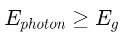
At the core of an LDR’s functionality is photoconductivity. This principle dictates that the electrical conductivity of a material can changes in response to light exposure. The process begins when light strikes the LDR, energizing electrons within the photosensitive material’s valence band—the energy state where electrons are normally present. This process can be described by the bandgap energy equation:
Electron Transition and Bandgap:
For electrons to contribute to electrical conductivity, they must transition to the conduction band, a higher energy state where electrons can move freely and carry current. This transition is not spontaneous; it requires that the incident photons have enough energy to overcome the material’s band gap, which is the energy difference between the valence band and the conduction band.
Charge Carriers and Conductivity:
When exposed to sufficient light, the photons’ energy breaks the covalent bonds within the photosensitive material, releasing both electrons and holes (the absence of an electron which acts as a positive charge carrier). These freed electrons and holes gain enough energy to jump from the valence band to the conduction band.
As the number of these charge carriers increases, the material’s overall resistance decreases, and its conductivity increases. The number of charge carriers is crucial for the reduction in resistance, which can be further quantified by:
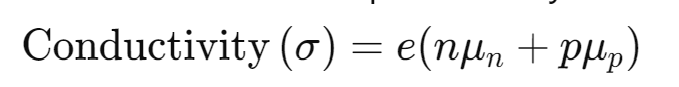
Where:
- e is the electron charge,
- n and p are the concentrations of electrons and holes, respectively,
- un and up are the mobilities of electrons and holes.
Light Intensity and Resistance:
The relationship between light intensity and resistance in an LDR is inversely proportional. Under dark conditions, the LDR exhibits high resistance, often in the megaohms range, due to the scarcity of free charge carriers.
However, as the light intensity increases, more electrons are excited to the conduction band, lowering the resistance dramatically. This unique property is what allows LDRs to act as effective light sensors, adjusting their resistance based on the ambient light levels. The relationship between light intensity and resistance is typically described by:
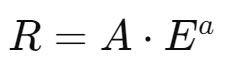
Where:
- R is resistance,
- E is illumination in lux,
- A and a are material-specific constants, usually reflecting the non-linear response of the LDR to light.
Applications of Photoconductivity:
This inverse relationship between light exposure and resistance is critical in applications requiring light sensitivity, such as automatic lighting systems, where lights need to be activated or deactivated based on the natural light available.
The principle of photoconductivity enables LDRs to perform reliably in environments where light conditions are continuously changing, providing an essential functionality in many technological applications.
Light Dependent Resistor Circuit
The functionality of an LDR can be demonstrated through a basic electronic circuit involving a relay, Darlington pair, diodes, resistors, and a bridge rectifier. This circuit utilizes a voltage supply from either a battery or a bridge rectifier that converts AC supply into DC.
A typical transformation in this setup involves stepping down the voltage from 230V to 12V through a transformer, followed by a bridge of diodes that rectifies AC into DC. This DC is then regulated down to 6V to supply the circuit.
In daylight, the LDR exhibits low resistance, allowing the power supply to pass easily through it. Since current prefers paths of lower resistance, it flows through the LDR rather than energizing the relay coil, keeping the connected light switched off.
Conversely, at night, the resistance of the LDR spikes, significantly reducing the current flow through the low-resistance path. This shift increases the base voltage of the Darlington pair above 1.4V, triggering the transistor and energizing the relay. As a result, the light turns on.
Circuit Implementation
In a typical LDR circuit, the device forms part of a potential divider network which is crucial for light level detection. When exposed to darkness, the LDR exhibits high resistance, resulting in minimal base bias for the connected transistor (TR1), keeping a relay in the ‘OFF’ position. As light increases, the LDR’s resistance decreases, raising the base bias voltage at V1 and activating the transistor.
This, in turn, energizes the relay to control external circuitry, such as turning on a light. The circuit’s sensitivity can be adjusted by replacing the fixed resistor R1 with a potentiometer VR1, allowing for precise control over the light levels at which the relay activates or deactivates.
For more sophisticated applications requiring higher sensitivity and stability, the LDR can be integrated into a Wheatstone Bridge configuration, using an operational amplifier to replace the transistor. This setup enhances the circuit’s response to light changes, making it more reliable under varying conditions such as temperature shifts or supply voltage fluctuations.
The design and functionality of LDRs make them integral to modern electronics, particularly in systems requiring responsive light sensing, such as automatic lighting controls. Their ability to adjust resistance based on light conditions offers both practicality and efficiency, while advancements in environmentally friendly materials further enhance their appeal in sustainable technology solutions.