Microstrip antenna are one of the most popular types of printed antenna. These play a very significant role in today’s wireless communication systems. Here we discuss microstrip antenna, their polarisation and radiation pattern, applications and upcoming trends.
The antenna is one of the critical components in any wireless communication system. The word ‘antenna’ is derived from Latin word ‘antemna.’ Since the first demonstration of wireless technology by Heinrich Hertz and its first application in practical radio communication by Guglielmo Marconi, the antenna has been a key building block in the construction of every wireless communication system. IEEE defines an antenna as “a part of a transmitting or receiving system that is designed to radiate or receive electromagnetic waves.”
Classification
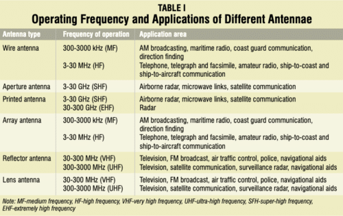
Antennae could be broadly classified as wire antennae, aperture antennae, printed antennae, array antennae, reflector antennae and lens antennae.
Wire antennae
This is the basic type of an antenna, widely used on top of the buildings, automobiles, ships and spacecrafts. These antennae are made into different shapes such as a straight wire (dipole), loop and helix.
Aperture antennae
These antennae are in the form of a slot or aperture in a metal plate and commonly used at higher frequencies (3-30 GHz). Typical examples are slotted waveguide antennae and horn antennae. These antennae are very useful for aircraft and spacecraft applications, because they can be conveniently flush mounted on the surface of the aircraft or spacecraft.
In practice, these antennae are covered with a dielectric material to protect them from hazardous environmental conditions.
Printed antennae
By definition, a printed antenna is one that is fabricated using standard photolithography technique. The most common version of printed antenna is microstrip antenna, which consists of a metallic patch above a ground plane. The shape and size of patch determine the frequency of operation of the antenna and its performance.
These antennae are more popular because of their low cost and ease of fabrication, and easy integration with circuit components. Printed antennae are inexpensive to fabricate using modern printed circuit technology, and are conformal to planar and non-planar surfaces. These antennae can be easily mounted on the surface of aircrafts, spacecrafts, satellites, missiles and even on handheld mobile devices.
Array antennae
In an array antenna, several radiators separated from each other are geometrically arranged to give desired radiation characteristics that are not possible to achieve with a single independent radiating element. The arrangement of array elements is such that radiation from individual elements adds up to give the maximum radiation in a particular direction or directions, and minimum radiation in other directions. In practice, individual radiators are arranged in linear or planar grid depending on the application.
Reflector antennae
These antennae are specifically used in applications requiring communication over long distances, such as outer space exploration and satellite communication. They are built with large diameters in order to achieve the high gain required to transmit or receive signals over very long distances. The reflector antenna usually uses a smaller antenna as the feed.
Lens antennae
In these antennae, lenses are used to collimate the incident divergent energy to prevent it from spreading in undesired directions. By choosing the appropriate material and setting the geometrical configuration of lenses, they can transform various forms of divergent energy into plane waves. Lens antennae are classified according to the material from which they are constructed or their geometrical shapes.
Microstrip antenna: the most common printed antenna
Microstrip antenna is one of the most popular types of printed antenna. It plays a very significant role in today’s world of wireless communication systems. Microstrip antennae are very simple in construction using a conventional microstrip fabrication technique. Microstrip patch antenna consists of a radiating patch on one side of a dielectric substrate (FR4) that has a ground plane (Cu) on the other side as shown in Fig. 1.
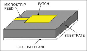
The patch is generally made up of a conducting material such as copper or gold and can take any possible shape like rectangular, circular, triangular, elliptical or some other common shape. The radiating patch and the feed lines are usually photo-etched on the dielectric substrate.
Microstrip patch antennae radiate primarily because of the fringing fields between the patch edge and the ground plane. For good antenna performance, a thick dielectric substrate having a low dielectric constant (<6) is desirable since it provides higher efficiency, larger bandwidth and better radiation. However, such a configuration leads to larger antenna size.
In order to design a compact microstrip patch antenna, a substrate with a higher dielectric constant (<12) must be used, which results in lower efficiency and narrower bandwidth. Hence a compromise must be reached between antenna dimensions and antenna performance. Excitation guides the electromagnetic energy source to the patch, generating negative charges around the feed point and positive charges on the other part of the patch. This difference in charges creates electric fields in the antenna that are responsible for radiations from the patch antenna.
Three types of electromagnetic waves are radiated. The first part is radiated into space, which is ‘useful’ radiation. The second part is diffracted waves, which are reflected back into space between the patch and the ground plane, contributing to the actual power transmission. The last part of the wave remains trapped in the dielectric substrate due to total reflection at the air-dielectric separation surface. The waves trapped in the substrate are generally undesirable.
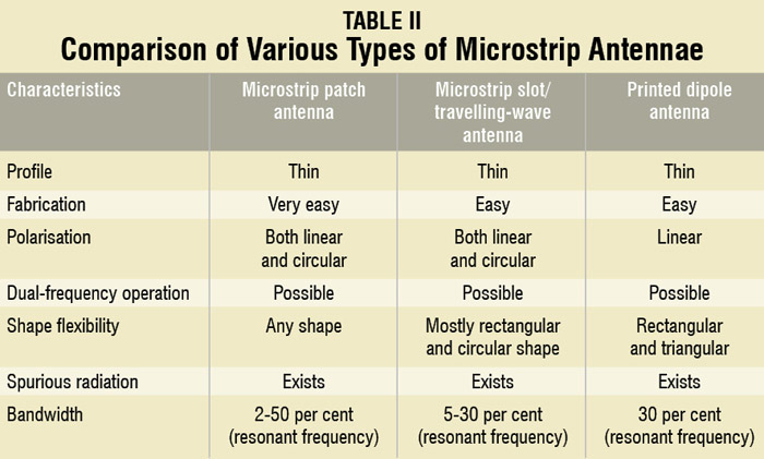
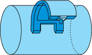
Different types of antennae have many different shapes and dimensions. Microstrip antennae can be classified into four subtypes:
- Microstrip patch antennae,
- Microstrip dipoles,
- Printed slot antennae
- Microstrip travelling-wave antennae.
Polarisation and radiation of microstrip antennae
The polarisation of an antenna is determined by the wave radiated in a given direction that is identical to the direction of the electric field. The instantaneous electric field vector traces a figure in time. This figure is usually an ellipse that has special cases. If the path of the electric field vector follows a line, the antenna is said to be linearly polarised. If the electric field vector rotates in a circle, it is called circularly polarised. To characterise the polarisation, axial ratio is used. It is defined by the following relationship:

Polarisation is said to be linear if T → ∞ or T = 0, and circular if T = 1.
There are two sub-types of linear polarisation: Vertical polarisation and horizontal polarisation. When ‘E’ field vector of the EM wave is perpendicular to the earth, the EM wave is said to be vertically polarised. When ‘E’ field vector of the EM wave is parallel to the earth, the EM wave is said to be horizontally polarised.
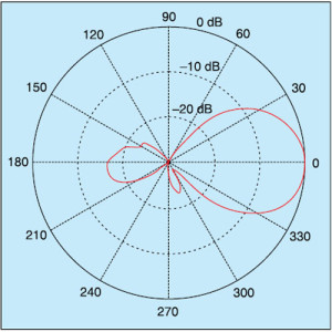
The radiation pattern is a graphical depiction of the relative field strength transmitted from or received by the antenna. Antenna radiation patterns are taken at one frequency, one polarisation and one plane cut. Patterns are usually presented in polar or rectilinear form with a dB strength scale. These are normalised to the maximum graph value of 0 dB and directivity is given for the antenna. This means that if side-lobe level from the radiation pattern were down -13 dB, and directivity of the antenna was 4 dB, side-lobe gain would be -9 dB.
Applications of microstrip antennae
Communication-based applications. Microstrip patch antenna finds several applications in wireless communication. For example, satellite communication requires circularly polarised radiation patterns, which can be realised using either square or circular patch microstrip antenna. In global positioning satellite (GPS) systems, circularly polarised microstrip antennae are used. They are very compact in size and quite expensive due to their positioning.
Microstrip antennae are also used in the fields of RFID (radio frequency identification), mobile communication and healthcare. Basically, an RFID system consists of a tag and a reader. Generally, it uses frequencies between 30 Hz and 5.8 GHz.
In telemedicine application, microstrip antennae operate at 2.45 GHz. Wearable microstrip antennae are suitable for wireless body area network. An antenna having gain of 6.7 dB and front-to-back ratio of 11.7 dB, and resonating at 2.45 GHz is suitable for telemedicine applications.
The IEEE 802.16 standard is known as WiMax (worldwide interoperability for microwave access). It can reach up to 48km (30-mile) radius with data rate of 70 Mbps. Microstrip antennae can resonate at more than one frequency. Therefore these can be used in WiMax-based communication equipment.
Some communication-based applications of microstrip patch antennae are radio altimeters, command and control systems, remote sensing and environmental instrumentation, feed elements in complex antennae, satellite navigation receivers, mobile radio, integrated antennae, biomedical radiators and intruder alarms, Doppler and other radars, and satellite communication and direct broadcast services.
Mobile communication
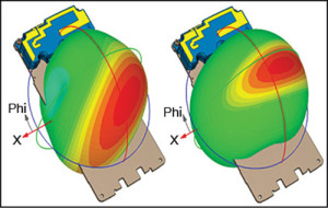
Mobile communication requires small, low-cost, low-profile antennae. In some mobile handsets, semiconductor-based diodes or detectors are used as antennae. They are much like p-n diode photo-detectors but work at microwave frequency. Many times omnidirectional antenna is used in mobile phones. There are different kinds of antennae like planar inverted-F antenna, folded inverted conformal antenna and mono pole. Also retractable whip antenna is commonly used in handsets.
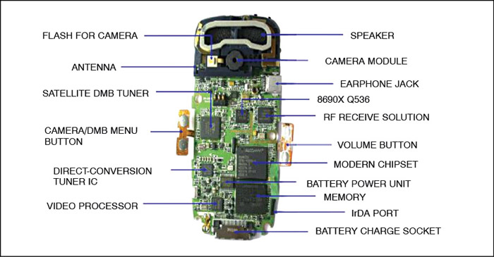
The phone is subdivided into roughly 60 components, each consisting of hundreds or even thousands of individual facets. The internal structure of a mobile handset is shown in Fig. 3.
Medical applications
In the treatment of malignant tumours, microwave energy is said to be the most effective way of inducing hyperthermia. The radiator to be used for this purpose should be light-weight, easy to handle and rugged. Only a patch radiator fulfils these requirements.
The initial designs of microstrip radiators for inducing hyperthermia were based on printed dipoles and annular rings that were designed on S-band (2-4 GHz). Later on the design was based on a circular microstrip disk at L-band (1-2 GHz). Two coupled microstrip lines with a flexible separation are used to measure temperature inside the human body. Fig. 5 shows a flexible patch applicator that operates at 430 MHz.
Textile antennae: recent research
There are some applications at present where antennae are used to continuously monitor biometric data of the human body. In order to do this, they need to be so close to the human body all the time that they can continuously monitor the biometric data and send the information to the outside world. If the antenna is hard, it cannot be kept always attached with the human body. An antenna made of textile material will not harm the human body and can be worn for extended periods. Wearable antennae will find use in healthcare, recreation, fire-fighting, etc.
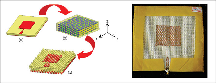
Textile materials are increasingly being used for development of flexible wearable systems due to the recent miniaturisation of wireless devices. For flexible antennae, textile materials form interesting substrates, because fabric antennae can be easily integrated into clothes.
In this special type of patch antenna, the radiating patch and the ground plane are made up of conductive textile material. The substrate too is a textile material with specific dielectric constant. As everything is made up of textile material, it is called textile antenna.
Textile antennae are still under testing, so they are rarely in focus.
Prof. (Dr.) S.A. Patil is professor and head, and Prof. P.C. Dhanawade is an assistant professor in E&TC deptt at DKTE Society’s Textile & Engg Institute, Ichalkaranji, Maharashtra.


Really informative. Keep up the good work
Sir your information is very useful to us.Iam going to give ppt on microstrip spiral antenna please send it’s working principle understandable
by 3btech
Hi,
I’m using a Flexible PCB antenna for my application, radiating on 2.4GHz. Is it possible to explain where the ground plane (reference plane) should be located, relative to the antenna and why ?
Thank you
Very good and informative post regarding microstrip antenna. That’s good.
very good and informative info. I am trying to decide my topic for phd. Here I got little info.
thanks
Really informative
Thank You for your valuable feedback.
Hello
Am working on microstrip antenna, using fr4 epoxy substrats, my antenna is multiband, but gain IS weak, who resolve this problem
very nice information
Thank You for your feedback.