


Lead sulphide detectors were used in older missile seekers, which forced missiles to look at stern engagements as the missile had to look at the hot turbine in the tail-pipe region to get sufficient signal to track the target. Modern missiles almost invariably use InSb or HgCdTe detectors.
Missile seekers would find it very easy and convenient to detect and track a hot target against a uniform benign cool background than doing so in the presence of clouds and extended IR sources. Sunlight reflected from the edge of a cloud would be as attractive a target, if not more, for the missile seeker than a jet aircraft. Reticle seekers handle all these issues by having very small instantaneous field-of-view (IFOV) and/or advanced signal processing.
Navigation to the target is the next important step after target acquisition and tracking. In

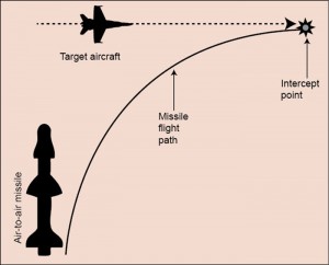
one method called pure pursuit, also called direct pursuit, the navigation technique ensuresthat the seeker is looking at the target continuously throughout the engagement duration till it eventually hits the target. In the case of pure pursuit engagement, the flight path is not the most direct one, as shown in Fig. 8, and the trajectory has an ever-decreasing radius-turn towards the end of the engagement. This poses a problem as the missile may not be left with enough energy to complete the turn in close-in range, allowing the target to escape.
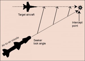
Proportional navigation or proportional pursuit, which is invariably followed in air-to-air missiles, allows the missile to have the shortest flight path towards the intercept, and therefore eliminates the need for a high-g manoeuvre towards the end. Proportional navigation flight path is established by a constant look angle as shown in Fig. 9 for a given constant missile velocity and assuming that target does not manoeuvre. In practice, target does manoeuvre and the missile velocity is also not constant through engagement duration. Therefore look angle is updated as and when required.
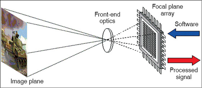

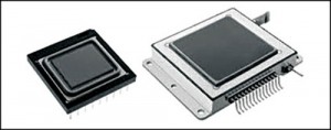
A variant of the reticle seeker is the pseudo imaging seeker. This seeker uses one or more detectors enabling both spatial and temporal information from reticle seekers. A small IFOV (≅ two milliradian) is scanned in a preset pattern and spatial information is used to determine the time instant of appearance of the target within the field-of-view. Detectors are therefore activated only within the time gate around the predicted time. This allows the missile to avoid large clutter and false targets outside the time gate. It also makes seeker highly immune to IR countermeasures. Imaging seekers use an array of detectors called imaging focal plane arrays (Fig. 10) instead of reticles to build an image of the scene in front (Fig. 11). The image may be created by scanning the scene and using a linear array or a two-dimensional staring array.
Imaging seekers are very expensive, require huge processing power and complex tracking algorithms. These are therefore employed only under demanding operational requirements. Reticle seekers, on the other hand, are less expensive and easy to manufacture and operate, and have a proven reliability and accuracy.
