


Response linearity predominantly decides the circular error probability (CEP). Immunity to false PRF codes and capability to stay locked to the desired code in the presence of false PRF codes enhances the probability of target hit. The former test is performed by irradiating the seeker head with a PRF code different from the programmed PRF code and later by irradiating the seeker head simultaneously with radiations of correct and false PRF codes.
Deployment configurations
Different deployment configurations are used for laser-guided munitions delivery, depending upon the nature of mission. The one illustrated in Fig. 2 uses a ground based laser target designator and aerially-delivered bomb. There can be other possible scenarios. For example, in another case, the laser target designator is located on another aircraft, which is not the one carrying the laser-guided bomb. Such a deployment scenario is depicted in Fig. 6.

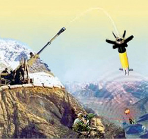
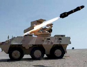
In yet another deployment configuration, the target is designated from a ground based designator and guided munitions are also launched from a ground based platform. This is true in case of cannon-launched laser-guided projectiles. This is depicted in Fig. 7.
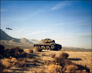
Yet another possible deployment configuration can be the one in which the laser target designation and laser-guided munitions delivery is executed from the same airborne platform as shown in Fig. 8.
While the delivery configuration shown in Fig. 7 is applicable to canon-launched laser-guided projectiles, the other three cases shown in Figs 2, 6 and 8 are different options used in the case of delivery of laser-guided bombs and missiles.
Laser-guided munitions delivery parameters
For a given value of sensitivity of the laser-seeker head (minimum power density required to be present in the seeker plane orthogonal to its optical axis for it to function satisfactorily), the guidance range depends upon the power density actually available at that plane. Available power density depends upon a number of parameters, prominent among them being peak transmitted power from the laser target designator, transmitted beam diameter, transmitted beam width full angle, laser target designator-to-target distance, target-to-receiver distance, atmospheric attenuation coefficient, target reflectivity, angle between transmitter line-of-sight and normal to the target, angle between receiver line-of-sight and normal to the target, angle between receiver line-of-sight and normal to receiver aperture, and target surface area.
Transmitted beam diameter and full-width angle decide the laser beam spot area at a given distance from the transmitter. The laser beam spot area is directly proportional to the laser beam width full angle and distance from the transmitter. Smaller divergence (consequently, lower laser beam width full angle) produces a relatively smaller laser beam spot area up to a longer distance and therefore is always desirable.
Power density at target location is given by laser power available at the target location, divided by the laser beam spot area at that location. Laser power reaching the target location depends upon transmitted laser power, atmospheric attenuation coefficient at operating wavelength and transmitter-to-target distance. Further, attenuation coefficient depends upon visibility conditions and the height of transmitter above sea-level.
Target irradiance, which is the laser power density on the target surface, is not the same as power density at the target location. This is due to the angle made by the transmitter line-of-sight and normal-to-the-target surface. Target irradiance is less than the power density at the target location by a factor given by cosine of this angle.
Target brightness is the laser power density per unit solid angle in the reflected beam. This depends upon target reflectivity and mechanism of reflection, whether it is specular or diffused or a combination of the two. Target brightness together with the solid angle subtended by the receiver aperture and the attenuation coefficient from target to receiver decide the power density available at the plane normal to the receiver cross-section. The actual power density available is further reduced by a factor equal to cosine of angle between receiver line-of-sight and normal-to-receiver aperture.
Received power is the product of power density multiplied by receiver aperture area. The value needs to be further multiplied by loss coefficient due to front-end optics.
Capabilities and limitations
Laser-guided munitions, with their diverse variants in surface and aerially-launched laser beam riders, canon-launched projectiles, aerially-delivered bombs and helicopter-launched missiles, are today the preferred weapons of precision attack by Armed forces worldwide. This has happened due to the constant upgradation of their capabilities over the years since World War II.
