


This method is best explained with the example of Hotel Taj Mahal in Mumbai where terrorists attacked. Assuming that the terrorists were still using RF communication for their coordination, it was possible to detect their signals and their precise origination, if multiple RF sensors (Fig. 2) were put in all corners of hotel building. Using cross-correlation technique the exact RF origination or emitting source, and hence terrorists’ locations, could be detected and they could be isolated and neutralised.
Though this technique is reactive and tactical, it can be really quick to spot the emitter and corrective actions can be taken to avoid larger damage. A better way, however, is to proactively monitor indoor areas of the sensitive buildings.
Fig. 3 shows a large hotel building with multiple floors and rooms. Each RF sensor scans its designated area and sends information to a common control location where all the RF-emitting sources (legal or illegal) in the hotel can be identified. Since sensors can time-synchronise their sweeps, the energy detection too gets synchronised. Power-level comparisons can then determine whether a transmitter is inside vs outside, and if inside, in which room.

This approach works well even if attenuation through the walls, ceilings and floors of buildings is substantial. The series of actions performed by this system in current example is summarised in Fig. 4.
Preventive use case for critical infrastructure protection
In preventive application of an infrastructure protection, a distributed network of RF surveillance systems can be used to perform the operation in remote mode, probably from network operations centre (NOC). The surveillance systems can be installed at various locations by connecting them on backhaul connectivity such as the Internet, 3G or a captive LAN network. These systems stay synchronised in time with GPS and therefore have the capability to geo-map suspicious emitters.
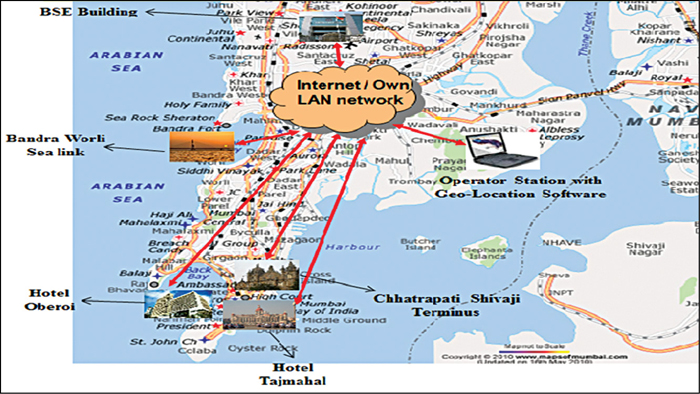
Let us take the example of Mumbai city, which has a large number of commercial buildings and other important establishments and tourist centres like BSE building, Hotel Taj Mahal and Chhatrapati Shivaji Terminus. A typical deployment and control scheme for Mumbai city is shown in Fig. 5, where RF sensors are located at strategic locations and their time-stamped data is pulled at NOC for network view of RF operations in the city. This is a true proactive monitoring because one would know of any incremental RF emission as soon as it happens.
The process of installation and commission of sensor-based systems remains the same as explained in Fig. 4. For better insight of the entire city, drive test with data recording facility can supplement areas in which the RF sensors cannot be easily deployed. The drive data and the stationary sensor data can be correlated at NOC and emitters can be determined.
Coastal/border surveillance
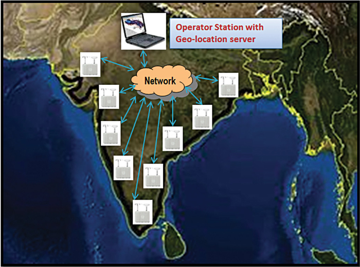
The third and final example is of very large- scale monitoring, which can be coastal or border surveillance systems. The system works on the same philosophy as described in previous section, with a difference that the RF sensors are located along the coast or border, and that the granularity of deployment is not as dense as in previous case. The deployment locations can be hill-top or resorts where uninterrupted data connectivity to NOC is available.
These systems also work 24×7 for continuous signal monitoring and analysis. The operational activities of this coastal/border application are the same as in Fig. 5, where the surveillance systems along the coastal or border area, with suitable backhaul connectivity, can cover the entire sensitive border area. Fig. 6 is an indicative example of such deployment.
The author is application engineer in Electronic and Measurement group of Agilent Technologies at Hyderabad. Along with Master of Engineering degree and specialisation in systems and signal processing, he has over 12-year experience in RF surveillance and communication, EW systems development, integration and testing
