We are nothing but a speck on the canvas of the universe; but this has not set a limit to our ambitions of exploring it. Space has always managed to fuel our interest from time immemorial and instigated us to continuously pursue it.
In this article we intend to introduce the basics of a satellite with respect to the electronics used in internal systems that is necessary to meet the purpose of a satellite (or payload). Before we actually move on to introducing satellites, let us first understand the challenges that Space has to offer.
Space is generally considered devoid of any medium. Here, the only means of energy transfer is through radiation. Conventional heat dissipation through convection and conduction, which characterises junction thermal resistance on Earth, is not applicable. New thermal models have to be created to analyse thermal performance.
A satellite orbiting in Space is showered with radiations from many sources, mainly the Sun. The Sun emits charged particles like alpha and beta that strike the satellite, causing transient effects in semiconductors. Uncharged gamma and ultraviolet rays hit the lattice of the semiconductor and disrupt its structure.
In spite of all these, the satellite has to still survive and operate. In order to describe this harsh environment and estimate the lifetime of satellites, we quantify these effects mainly into total ionisation dose (TID) and single-event effects (SEEs).
TID is defined as the cumulative amount of radiation energy that the semiconductor can handle before it fails. It is measured in Rad (unit of radiation).
SEEs like latchup, upset, bit flip, gate rupture and transients are measured in mega electron volts (MeV), which signifies the radiation energy required to cause SEE.
Semiconductors for Space undergo a special process called radiation hardening in order to attain a higher immunity to radiation effects. The extent of hardening depends on the orbit and criticality of the mission. A common number, referred to as a rule of thumb, for TID is 100kRad and 100MeV for SEE for a deep-Space mission.
System designs in the satellite can be classified into mission-critical and non-mission-critical. Mission-critical applications include those designs whose malfunction can cause an irreversible damage to the satellite and may also result in mission failure. These include sub-systems like attitude determination and control system (ADCS), onboard control and data handling (OBD and DH), electronic power system (EPS) and actuator electronics. These are explained in detail in subsequent sections.
Non-mission-critical designs typically include systems that are not continuously used throughout the life span of the satellite. These include payload sub-systems like cameras and imaging devices. The launch vehicle can also be put under this category as its utility ceases after it has put the satellite into orbit and is no longer needed for satellite operation. Damage to the satellite from these non-mission-critical designs is minimal.
With this basic understanding of Space and systems, we will study more about satellites. A satellite is defined as anything that orbits a planet. Satellites can be mainly categorised as:
Low-Earth orbit. These fly at low altitudes of about 160km and are used for Earth observation and surveillance.
Geostationary. These orbit directly above the Equator with a period equal to one Earth day, and as a result appear to be fixed. These are widely used for TV communication.
Geosynchronous. These are very similar to geostationary ones except that their orbit is centred over a fixed latitude and is in the shape of number eight (8).
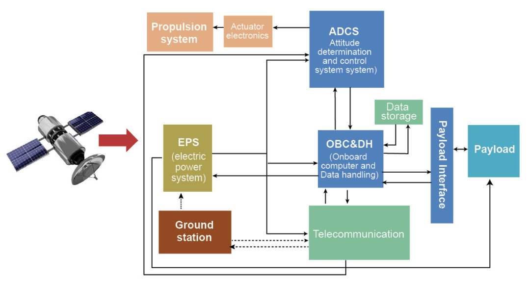
Polar. These orbit Earth from pole-to-pole, providing meteorological information. A satellite is launched for a particular mission, which makes up the payload of the satellite. This payload is carried into the orbit as a part of the satellite by the launch vehicle. If we consider a typical satellite, it would contain the blocks shown in Fig. 1. Each of the sub-systems has its own significance and is an indispensable part of the satellite.

Attitude determination and control system. This is the navigation and stabilisation system of the satellite. Attitude determination requires multiple sensors like Sun sensor to determine satellite’s position with respect to Sun, star sensors to identify common stars that are used as reference for navigation, magnetometer, GPS, accelerometer, gyroscope and horizon sensors. All these sensor inputs are analysed by the control system to stabilise and keep the satellite on the designated path, counteracting external torque and forces.
Telecommunication. This sub-system is used for RF communication either with the base station or between satellites. It contains a modulator block to transmit data and a demodulator to receive and process the data. This block is often used to control the satellite from the ground station and to transmit/receive data to/from the satellite.
Electronic power system. The satellite has a lot of electronic content in it, which needs to be powered over its lifetime of operation. This sub-system mainly contains two sections: generation and battery charging, and distribution and monitoring.
The sub-system uses solar panels to generate electricity from Sun and stores it in batteries. A monitored power bus from the battery is distributed across other sub-systems.
This voltage is usually 28V, 42V or 70V. It is converted to various other voltage rails as per the demand from each of the sub-systems.
Onboard computer and data handling. This is the brain of the satellite. It has a processor, RAM and associated memories that enable it to perform a variety of functions. It acquires data from the payload and processes it based on the running algorithm.
It can then store this data onboard and/or relay it to the ground station. Along with this, it aids ADCS sub-system to process sensor inputs to decide the correct course of action. It also monitors other related sub-systems and keeps a track of the running processes. Usually, the sub-systems are connected on a standard 1553 or low-voltage differential signaling interface.
Actuator and propulsion electronics. This is an electromechanical system that implements the decision taken by ADCS sub-system. It usually fires the booster stage or enables the motor drives that bring about rotation of the resonant wheels, which adjust the course of the satellite.
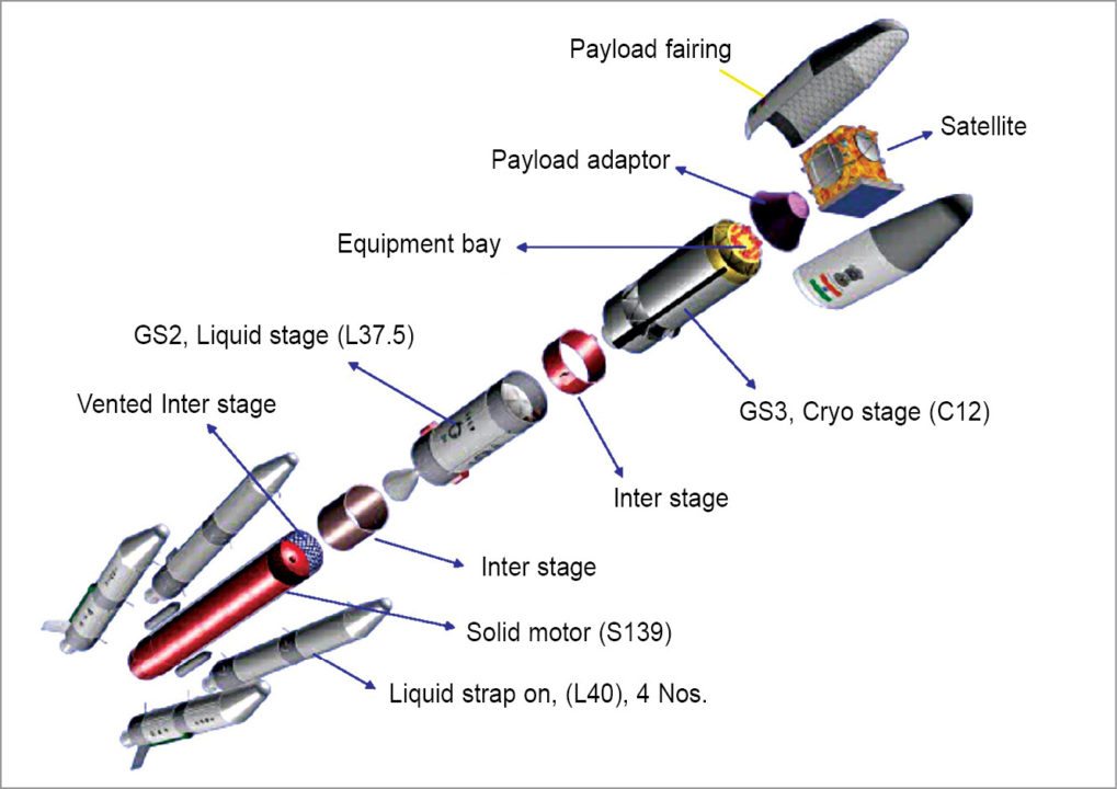
Payload. This is the sole purpose of the flight mission. The type of payload determines the type of satellite. Humans can also be part of the payload. A few common types of payload include meteorology, GPS system, satellite based telecommunication and synthetic aperture radar used to map a planet’s surface with great degree of accuracy. Fig. 2 illustrates a full-blown satellite along with its launch vehicle.

The term satellite might sound intimidating at the beginning but we hope that the article has made it a better discernible concept using the sub-systems approach. Each sub-system described here has a number of smaller systems within it. Harmonic interoperation of these systems ensures success of the mission, which is ultimately another step of man towards exploring eternal Space.


Nice way to explain.
Thank you for your feedback.