An advanced approach has been developed to monitor and control small grids for better power utilization and fault detection. Power available at the grid which can come from multiple sources like solar, power plants, generators can be feed to the users intelligently. Depending upon the availability of power, it can be distributed priority wise among different types of users like hospitals, street lights, water pumps etc. All the related decision has been taken by a centralized control system or a smart system controller called Multi Utility Controller.
It not only includes operational controls but also energy measurement elements to analyze for better power distribution. Various parameters and usage information can be fetched using Power Line communication (PLC) from various smart utility meters like energy meter, gas meter, and water meter to generate bills and manage tariffs. The same controller can be used to communicate with street lights wirelessly for better usage and troubleshooting. This can help in saving power by controlling On/Off, light intensity remotely. All gathered information can be uploaded on server using LAN or GPRS connectivity for power analysis.
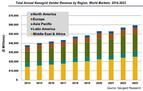
In developing countries like India, most of the population lives in small villages which have very limited availability of electricity or even does not have electricity at all. Smart Nano grid is the only solution to make them self-dependent for electricity and to face current challenges. These are digitally monitored energy systems that deliver electricity, water, gas from generation sources to points of consumption.

They optimize power delivery and facilitate two-way communication across the grid, enabling end-user energy management, minimizing power disruptions and transporting only the required amount of power. The result is a lower cost to the utility and the customer, more reliable power, and reduced carbon emissions.
Smart Nano Grid Architecture
Nano grids are very small grids to serve a building or village with few number of houses with a typical load of 100 kW for grid-tied systems and 5 kW for remote systems not interconnected with a utility grid. In the current architecture, smart grid controller has been proposed which not only handles the power distribution but also control and monitor smart street lights. All the utility meters like energy meter, gas meter, water meter etc. are also connected with this controller for billing and other consumption analysis.
Smart Nano Grid Key Components
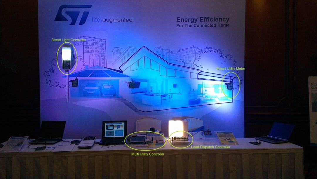
1. Multi Utility Controller
2. Load Dispatch Controller
3. Street Light Controller
4. Smart Utility Meters
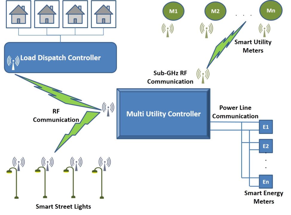
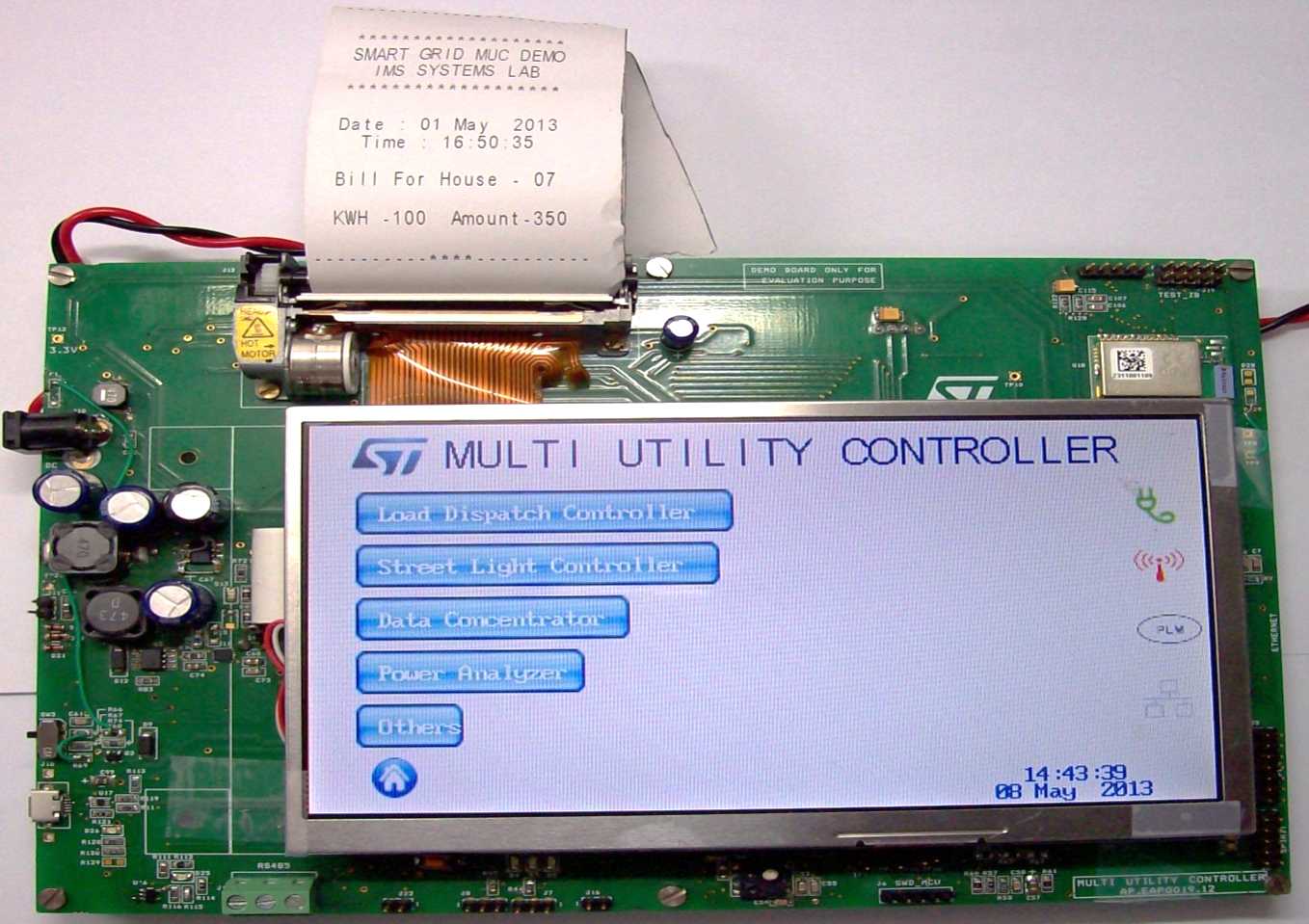
Multi Utility Controller (MUC) is an adaptable controller system for a smart Nano-grid environment. It is a portable in size and battery operated so that utility worker can keep it along with him in the field. It has a LCD display to monitor the status of the grid and a user interface for grid control. Multiple type of communication protocol are available to communicate with different types of utility meters. All the gathered information is then uploaded on the server.
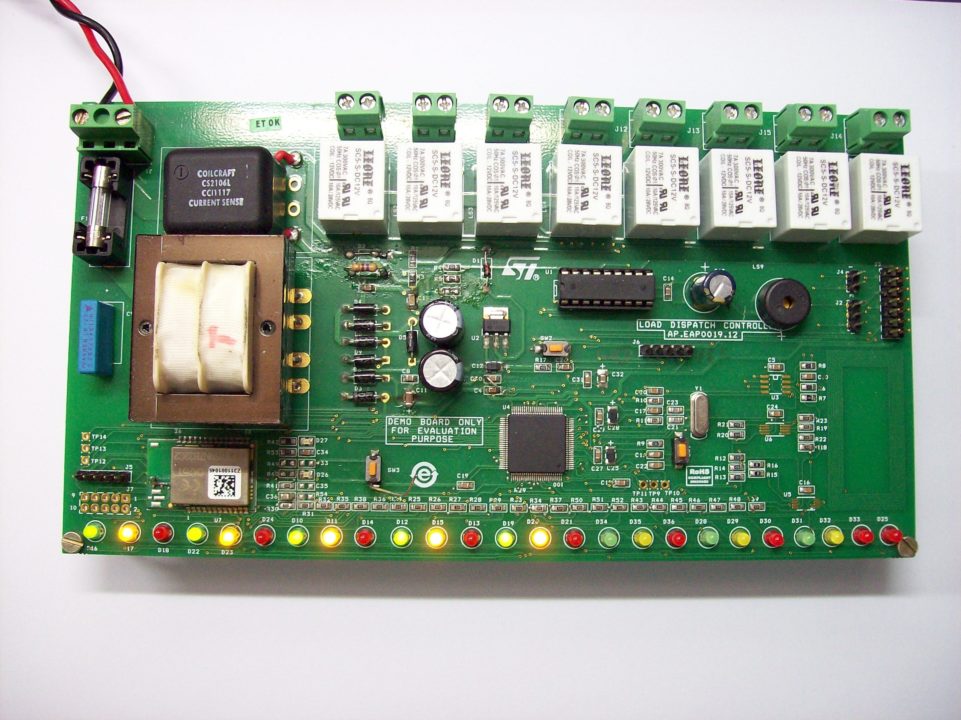
Load Dispatch Controller delivers power to different houses depending upon the power available. It has multiple relays to control the electricity delivery of each house. Status of all the houses and current power parameters like voltage, current has been sent to MUC using wireless communication. MUC analyze these parameters and sends command to load dispatch controller to control the distribution of available power.
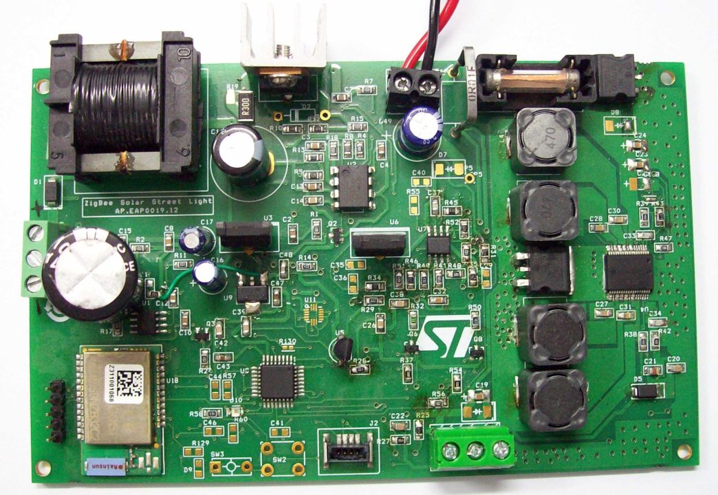
Street Light Controller is a controller system for managing street lights using wireless communication. It is a battery operated system which takes its power from solar light for charging & then to run the LED light at night. It has the intelligence to monitor different system faults and then to send fault status to MUC.
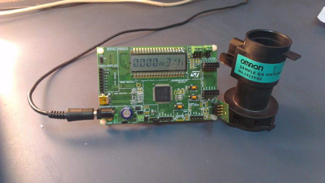
Smart Utility Meters reads various usage information including total consumption parameters, instantaneous consumption, tariff-wise consumptions etc. along with configuring various parameters i.e. Configuration parameters, maintenance parameters, tamper management, tariff settings etc. sub–1GHz wireless communication or wired Power Line Communication helps meters communicate directly with MUC.
MUC System Architecture
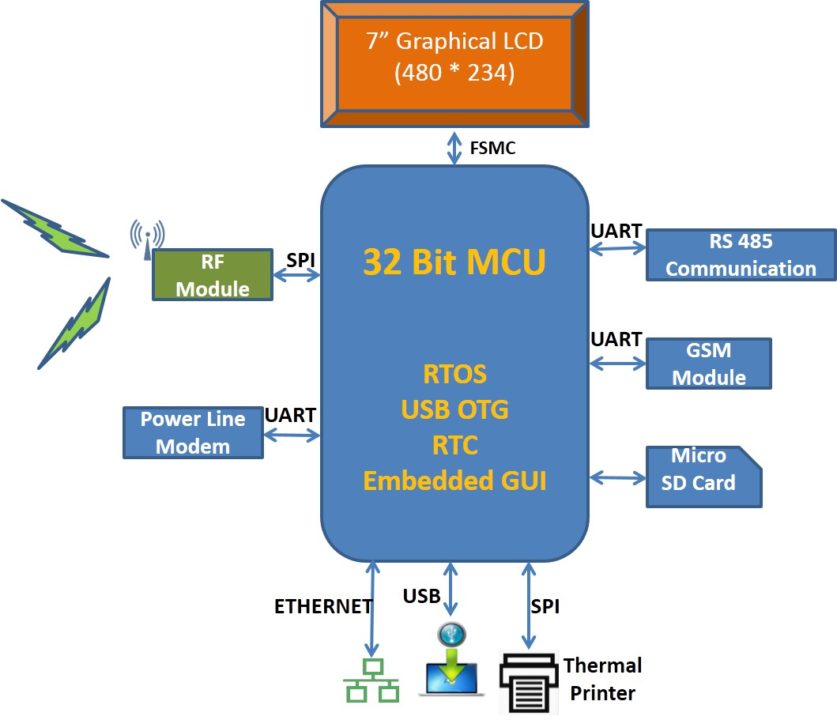
MUC system has been designed around STM32F4 series microcontroller from STMicroelectronics. It is the high-performance ARM®Cortex-M4 32-bit RISC core operating at a frequency of up to 168 MHz suiting for this application. On chip 1 Mbyte Flash memory along with 192 Kbytes of SRAM met the memory requirements.
A 7.0 inch Amorphous-TFT-LCD (Thin Film Transistor Liquid Crystal Display) with a Resolution of 480(R.G.B) X 234 pixel is used to display the various parameters and to take the required inputs. MCU’s on Chip FSMC peripheral has been used to interface the LCD display.2-inch wide paper FTP-628 MCL Thermal printer is used to print the bills at customer premises. It can print at 80 mm/s (640dotlines/s) with high resolution printing of 8 dots/mm. It has been interfaced with controller using SPI protocol. L9935 is a motor driver that drives thermal printer motor. It is a two-phase stepper motor driver circuit suited to drive bipolar stepper motors. The device can be controlled by a serial interface (SPI). All protections required to design a well-protected system (short-circuit, over temperature, cross conduction etc.) are integrated in it.
System can be monitored and controlled from remote location using Ethernet interface STE100P Fast Ethernet physical layer interface for 10Base-T and 100Base-TX applications. It also provided Media Independent Interface (MII) for easy attachment to 10/100 Media Access Controllers (MAC) and a physical media interface for 100Base-TX of IEEE802.3u and 10Base-T of IEEE802.3.
GSM module can be plugged on MUC for remote connectivity using GPRS.
OTG USB Communication makes the system work both as host as well as the device. So MUC can be used to fetch images from pen drive or can be connected with PC to show different parameters on PC for further analysis.
SPIRIT1 is a very low-power and High-Performance RF transceiver, addressing RF wireless applications in the sub-1 GHz band. It can operate at 169, 315, 433, 868, and 915 MHz. SPIRIT1 module communicates with MUC using SPI protocol for wirelessly data exchange with the utility meters.
FSK, PSK multi-mode power line networking system-on-chip device ST7580 has been interfaced with MUC to monitor data coming from Energy meter using PLM Communication.
MUC Power Management
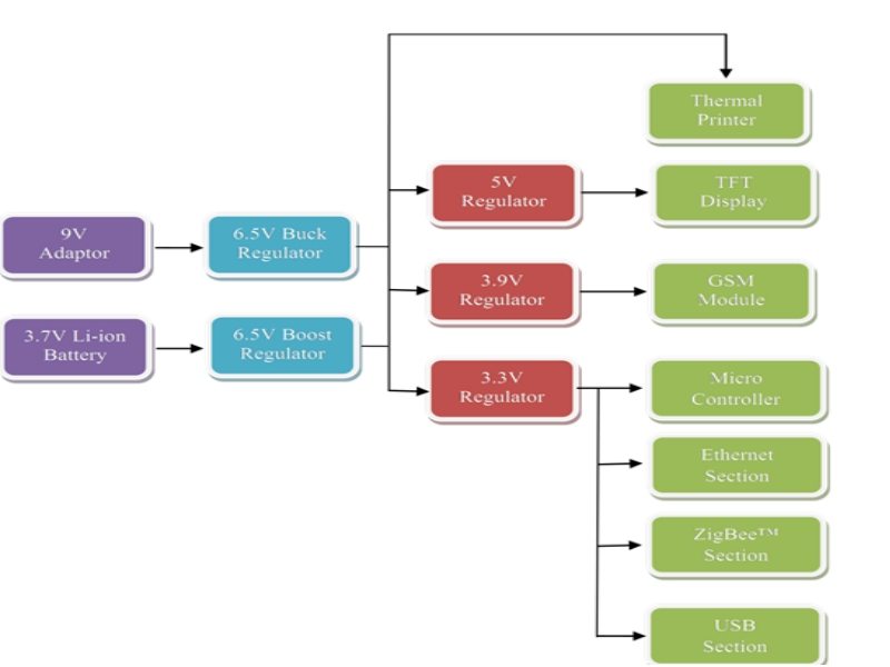
MUC can be powered by both, a +9V power adaptor as well as a 3.7V Lithium Ion battery.
Power adaptor along with powering the system also charges the Li-Ion battery using L6924D battery charger IC. It works in Linear Mode, and charges the battery in a constant current/constant voltage (CC/CV) profile. Various parameters, such as pre-charge current, fast-charge current, pre-charge voltage threshold, end-of-charge current threshold, and charge timer has been configured. A 22nF Capacitor is connected between T_PROG and ground to set maximum charging time. During constant current charging mode, charging current is programmed to the value around 900mA. This value is selected by connecting a 1% 13.5K resistor Rprog across I_PROG pin. When the battery voltage approaches the charge voltage (4.20V), the charger enters into a constant voltage charging mode and the charging current decreases. When the current level reaches the end-of charge level the charger enters in maintenance mode.
Adaptor supply is step down to 6.5V using L5987 switch down switching regulator with 3.5A (minimum) current limited embedded power MOSFET, so it is able to deliver up to 3 A current to the load depending on the application conditions.
Similarly Li-Ion battery supply is step up to 6.5V using STLDC08. 6.5V supply is used to drive thermal printer. Also this supply is given to different linear voltage regulators.
3.3V supply is generated using LD29150DT33 which provides 1.50 A of maximum current. This 3.3V supply drives Microcontroller section, Ethernet Section, Spirit1 Section, USB Section etc.
Fixed 5V is generated using LD29150DT50 required for TFT Display & Thermal printer.
Adjusted LD29300P2MTR voltage regulator generates 3.9V required to drive GSM module.
Multiple Use cases and Benefits
With the increasing demand of power, distribution of power really becomes a big challenge for related distribution companies. Smart controller can be the best candidate to help in handling with this. Smart controllers can help in accessing the information related to the power consumption patterns of the multiple users to manage the electricity distribution more efficiently.
With the remote connectivity, utility worker can diagnosis or troubleshoot without going to location where fault has occurred. This not only save the effort involved but also the time to troubleshoot the problem.
Dynamically changing tariff can also be integrated in the system to reduce the peak time load consumption by increasing the per unit price for the peak duration. Also end users can track the energy consumption online to view his energy consumption profiles monthly, day wise or even hour wise to help him better plan their usages. This can benefit both the end user and the utility company.
Conclusion
Smart system controller can help both the power generation and distribution companies in better planning and management. This can eventually help in reducing the carbon emissions associated with the generation and distribution of electricity. In future these adaptable systems can be integrated with smart devices and home so that devices can automatically respond to grid condition. This can help in making a very efficient broad ecosystem to realize the full potential of a grid system.