


When looking at the coating of an assembly, one must distinguish between the testing, examination of the coating process, the coating result, functional testing of the assembly and qualification testing of a coating.
The coating result can be examined, for example, in accordance with the rules of J-STD-001 and IPC-A-610, or also in accordance with the Workmanship Standard of NASA, NASA-STD-8739-1.

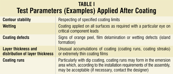
Tests carried out after coating of the assembly
Besides fulfilling the underlying technical specifications, the following is generally demanded for a coating in accordance with J-STD-001 and NASA-STD-8739-1:
1. The coating shall be uniform and even in colour, layer thickness and surface; minor pull back (edge loss) from sharp edges and angles is permissible unless otherwise specified in the technical specification
2. The coating shall properly adhere to all coated surfaces
3. Thorough drying or curing
4. Homogeneous coating film
5. Surfaces may be coated only in accordance with the respective specification
6. The coating film must be free from bubbles which have an impact on the protection provided by the coating
7. The coating film shall be free from voids, bubbles or inclusion of impurities that are likely to expose electric conductors and/or have an influence on the potential distances
In addition, IPC-CC-830B requires that the coating film shall be free from harmful substances, bubbles, pinholes and/or voids, wrinkle formation, crack formation and delamination.
The conformal coating result shall be smooth and even, homogeneous, transparent and tack-free at ambient conditions. As far as the formation of bubbles in the coating film due to a specific application method is concerned, the IPC handbook IPC-HDBK-830 gives a practical hint. Bubbles shall be avoided by all means in the dried coating film; since this is not always possible for different reasons, it recommends the following:
“Bubbles are generally acceptable provided their size does not exceed 50 per cent of the distance to the conductor from the spot where they occur, and they do not expose any conductor, bridges or adjacent conductor surfaces.”
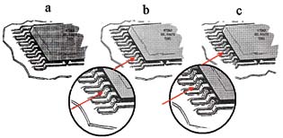
The NASA-STD-8739-1 released in 1999 gives visual assistance (see Fig. 1) by describing the frequency of bubble formation.
According to NASA-STD-8739-1, the bubbles of Fig. 1(b) shall “not exceed 0.76 mm.” However, given the progress in miniaturisation since the standard was published in the year 1999, this statement has to be considered outdated. The IPC-A-610D view on bubbles is as follows: “The inspection shall be done with the naked eye. If this inspection clearly confirms the suspicion of bubble formation, the parts in question shall be viewed with a maximum of 4x magnification (e.g., by a 3x ESD-protected loupe), according to IPC-A-610D, 10.5.2.2. This magnification is based on the description of J-STD-001D. Coating materials that contain a fluorescent pigment may be examined under black light to verify the coating, and white light may be used as an aid for examining the complete coverage of the coating. If the bubble is acceptable, the part in question may be released, but if the bubble turns out to be a defect, the part has to be rejected and the defect recorded.
After the safe launch of the application process, its stability regarding bubble formation has to be assessed. While the visual inspection can be performed without destroying the assembly, this does not apply without restrictions when the physical and/or chemical properties or resistances are determined. Depending on the layer thickness, a coating film achieves its maximum property values after a more or less long drying time. The property values have to be tested, in accordance with DIN 46449, at the earliest 96 hours after becoming tack-free. Due to its importance, the following is cited from DIN 46449; section 5.2 ‘Time of the tests’:
“The tests according to sections 5.5 to 5.12 are carried out, unless otherwise mentioned for the individual test procedures, on unaged test specimen, in case of air-drying coatings between 48 and 96 hours after reaching drying stage 3 (according to DIN 46456 Sheet 1, Edition January 1970, Section 6.7; VDE 0360 Part 1165) and in case of oven-drying coatings at the earliest 24 hours after drying.”
Drying/curing of a minimum of 96 hours at ambient temperature (after becoming tack-free) is recommended in order to ensure the drying and curing even of slightly thicker layers, e.g., at/under components or drip noses.
In case of oven curing, a minimum of 24 hours as mentioned above have to be observed. Depending on the component geometry, layer thickness, etc more than 24 hours may be necessary under certain circumstances until the maximum property values are achieved.
Visual inspection
After the coating and drying/curing is completed, the coating result is inspected visually for its evenness and completeness. This inspection can be made based on random samples or by verifying individual pieces if the contours or demands are of a complex nature. For large quantities, or in case of in-line productions, optical control systems are employed to a growing extent. These optical control systems use a scanning technique similar to that of automatic component mounting. The scope of the visual inspection results from the specifications (customer requirements) and from internal requirements such as the coating plan and the quality parameters. The visual inspection may be done without referring to any optical aids—thus by the naked eye—or by means of a microscope or magnifying lens. For comparative tests, J-STD-001D recommends a 1.75- to 4-fold magnification.
If the conformal coating contains a UV marker or a fluorescent dyestuff, it is recommended to carry out the inspection under so-called ‘black light.’ Should a microscope be used for optical inspections, a ring light has proved to be a good choice, since its segments can be individually connected or disconnected. It allows, for example, to selectively fade out debilitating reflections. These ring lights are also available with the appropriate UV-LEDs.
‘Black light’ is a colloquial term for a UV-A radiation generated by low-pressure gas discharge lamps or LEDs in the wavelength range between 350 nm and 370 nm. This UV-A radiation excites fluorescent substances, e.g., some papers with added pigments or dyestuffs, to glow. This ‘black light’ inspection, however, is neither suited to detect microscopic pinholes or bubbles nor to determine the layer thickness.
It should be noted here that not just the coated areas have to be checked but also such areas which must remain uncoated; any splashes in this area, for example, are easily detected by means of black light.
Adhesion test
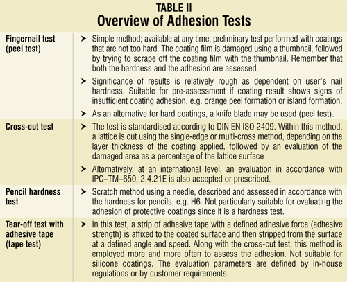
The adhesion of the coating film after drying/curing can be tested by using various methods. An overview of common adhesion tests is given in Table II.
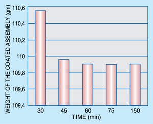
Determination of drying stage
The determination of the solvent content by checking the weight serves the purpose of easily ascertaining the drying stage after the evaporation of solvents, yet it does not contribute to ascertaining the degree of curing in terms of cross-linking of polymers. Within this test, the coated assembly is weighed after a defined drying time; e.g., after 30 minutes at 80°C. Following this, the respective weight is determined in intervals of 15-minute drying time (the drying temperature for this test must be chosen in accordance with common practice—in this example, 80°C). If the weight no longer drops, the assembly is stored at ambient temperature for two hours and then weighed again. On the basis of this data, the necessary drying time can also be determined.
Functional tests
Following the application of the protective coating, the coated item is usually either further processed or, in case of contract coating, dispatched to the customer. In the scope of quality control, fault reduction and monitoring of the process chain, a so-called functional test is performed after protective coating. Once the tests described above are completed, an electrical test or a test combining function and climatic loading is carried out. Quite often, a mechanical test is also included, in order to simulate the subsequent process of fitting into housings. In addition, the functionality of contact points such as plugs, test points and relays is verified. In view of the intended application, the functional test is often combined with a climatic and/or thermal loading. For this purpose, the relevant conditions of temperature and moisture are adjusted in a climatic chamber before the functionality of the assembly is checked. Burn-in test is a quality control tool used to check either complete devices or individual components of devices. Experience has shown that defective devices not identified in the manufacturing process will fail after a short time of continuous operation and/or when operated under extreme conditions.
In order to detect hidden defects, a burn-in with thermal cycling is the suitable method to reduce early failures in the bathtub curve. As described in coating qualification, the stress factors are:
1. Temperature range (temperature lift, e.g. –40°C/+85°C)
2. Thermal cycling speed
3. Dwell time at peak temperatures
4. Number of temperature cycles
A burn-in may be realised as an individual station or as a tunnel system. For the two temperature peaks, and may be also in the dewed heat-up phase, functional tests are performed. To ensure traceability of the burn-in, the following points should be recorded:
1. Identification and assignment of the test specimen
2. Test temperature and dwell times
3. Results of functional tests
4. Evaluation of the test specimen (whether ‘ok’ or ‘not ok’)
Such climatic tests are often made as a serial arrangement where they are combined with the electrical function test as shown in Fig. 3. Also, primary stress factors related to moisture load are evaluated. If there is a risk of dewing, an alternating climatic load should be preferred over a constant climate load. In case of an alternating climate load, it must be ensured that dewing actually takes place as required, by using a dewing sensor for verification in case of doubt. These tests may also be performed in the scope of controlling the coating quality by random samples.
Climatic loads may be chosen as follows:
1. Thermal cycling: –40°C/+85°C,
6 cycles with 3-7K acceleration
2. Climate: 40°C/93% R.H., 6 cycles
3. Thermal shock: –40°C/+120°C, 24 cycles
Also check Examsnap, a community of IT certification exam takers committed to sharing their exam knowledge and experience with their peers, as well as those looking for free information sources to study for their Certification exams. Our members share their knowledge on IT certification exams in convenient VCE files.
This article is an extract from the book titled ‘Conformal Coatings for Electronics Applications’ by the author. The sources of information are mentioned in the book
