There are some interesting developments happening in the field of aviation. Flying cars of different configurations, currently in limited production, are expected to save billions of litres of fossil fuels now wasted in traffic jams in metros all over the world. Like highways, now skyways are also being planned. There are many new entrants in the business jets manufacturing sector. Production of medium- and long-range jets has been doubled to cater to the increasing air traffic all over the world.
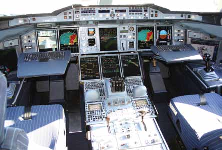
Integrated avionics software and large displays are creating cockpits that offer pilots dramatic new perspectives. They include QWERTY key-boards and trackballs, interfacing with a graphical ‘point-and-click’ display navigation system.
A conventional cockpit relies on numerous round dial mechanical gauges to display information. Today, glass cockpits look and behave like computers with Windows data that can be manipulated with mouse and other click devices—familiarly known as WIMP (Windows, Icons, Menus, Pointers) technology. Touchscreens in the cockpits are enhancing the entry and observation of flight data more efficiently.
With the increasing processing power of on-board computers, additional features like electronic flight bags (an electronic information management device) and electronic fl bags (device storing engineering and commercial data) are being incorporated in cockpits, which drastically reduce the enormous documentation.
Let’s take a detailed look at these and other advancements in cockpit design.
Digital data buses
Today, like the majority of desktop computers, most operational and flying cockpits have human-machine interfaces, that are based on WIMP interfaces. Some of them standardise upon the ARINC 661 international standard digital data bus for interactivity management.
Digital data buses greatly improve the intercommunication between aircraft systems and cockpits. Previously, large amounts of aircraft wiring were required to interconnect each signal with the other equipment. As systems became more complex and more integrated, this problem aggravated. Digital data transmission techniques use links that send streams of digital data between equipment. These data links comprise only two or four twisted wires and therefore the interconnecting wiring is greatly reduced.
Common types of digital data transmission are single-source single-sink, single-source multiple-sink, multiple-source multiple-sink and fibre-optic data buses.
Single-source, multiple-sink. In this technique, one transmitting equipment can send data to a number of recipient equipment (sinks). ARINC 429 is an example of this data bus which is widely used by civil transports and business jets.
Multiple-source, multiple-sink. In this system, multiple transmitting sources may transmit data to multiple receivers. This is known as a full-duplex system and is widely employed by military users (MIL-STD-1553B) and the Boeing 777 (ARINC 629).
Major digital data buses in use today are:
1. ARINC 429 (A429)
2. MIL-STD-1553B, also covered by Def Stan 00-18 Part 2 and STANAG 3839
3. ARINC 629 (A629)
4. Fibre-optic bus
Of these, A429 and A629 are commonly in use on civilian aircrafts. MIL-STD-1553 is a military standard.
Integrated flight management system
Today, the glass cockpit uses several displays driven by integrated flight management systems that can be adjusted to display flightinformation as needed.
Auto-pilots integrate both fly-by-wire of flight controls and power-by-wire engine controls. These generally divide a flight into taxi, take-off, ascent, level, descent, approach, landing and taxi phases. Landing on runway and controlling the aircraft on rollout, i.e., keeping it at the centre of the runway, is CAT-3B landing, used on the majority of major runways today. Landing, rollout and taxi control to stand is CAT-3C.
Basically, integrated flight control systems should control the primary and secondary flight control surfaces. Primary control surfaces are pitch, yaw and roll motions of the aircraft. Secondary flight control surfaces help the aircraft to take off and land like leading-edge slats and spoilers. The horizontal stabiliser at the rear controls the pitch motion, the rudder yaw or direction, while the Ailerons control the roll motion of the aircraft.
On-board computers with associated software control the flight of the aircraft. Both primary and secondary flight control surfaces are automatically controlled, reducing the workload of the pilot.

The autopilot controls the engine power and is familiarly called power-by-wire concept. Full authority digital engine control (FADEC) enables matching of air-fuel ratio at various speeds, loads and altitudes to produce optimal power and reduce emissions. FADEC is integrated to the autopilot.
GPS devices in cockpits
GPS provides geographical location in term of latitude and longitude of the destination.
Pilots can use the touchscreen panel to check information about nearest airports, weather reports, runway patterns and distance. When a plane lands, a button push gives the pilot the more familiar car GPS screens. GPS systems used in aircrafts now have an accuracy of 1 cm. This is accomplished by using GPS in conjunction with accurate altimeters and differential GPS. The differential GPS interacts with airports (base stations) in addition to satellites.


