


 Here is a simple and inexpensive visitor counter circuit that you can build easily. Visitor counters available in the market are generally expensive and are based on microcontrollers, which are difficult to program.
This circuit comprising a transmitter and a receiver can count up to 99 visitors automatically. It is built around CD4026 (decade counter and 7-segment driver in the same IC package).
Visitor counter circuit
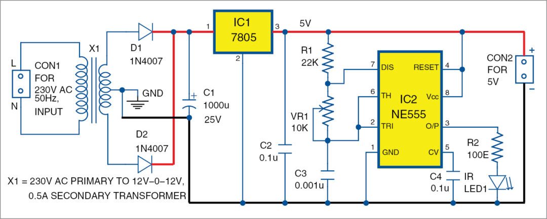
The circuit diagram of the infrared (IR) transmitter unit for the visitor counter is shown in Fig. 1. It comprises transformer X1, 1N4007 rectifier diodes D1 and D2, 1000µF (25V) filter capacitor C1, 7805 (5V) voltage regulator IC1, NE555 timer IC2, IR LED (LED1) and some other components. The transmitter generates 38kHz carrier frequency.

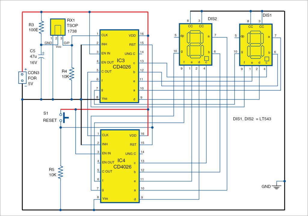
The receiver unit with 7-segment displays is shown in Fig. 2. It comprises two CD4026 ICs (IC3 and IC4), reset switch S1, two 7-segment common-cathode displays DIS1 and DIS2, TSOP1738 IR receiver RX1 and a few other components.
Power supply for the circuit(s) is made up of transformer X1 that steps down 230V AC mains supply, full-wave rectifiers comprising diodes D1 and D2, filtering capacitor C1 and 7805 regulator IC1 to maintain a constant 5V DC at the output. The 5V DC is used by the transmitter and also fed to the receiver section by connecting CON2 to CON3.

Decade counter IC CD4026 or CD4033 (whichever is available) can be used as counter-cum-display driver.
As this project is designed for a 2-digit counter, it counts up to 99 only. The counter uses two 7-segment common-cathode displays (LT543). For one’s position it uses a CD4026 (IC3) and a 7-segment common-cathode display LT543 (DIS1). For ten’s position it uses another CD4026 (IC4) and another similar 7-segment display (DIS2).
The IR transmitter circuit is designed for commercial application. Its NE555 timer can be wired as a one-shot or astable multivibrator. In this circuit it is configured in astable mode. For that, we use fixed 22k resistor R1, 10k potentiometer VR1 and 0.001µF capacitor C3 for generating exact 38kHz carrier frequency.
The formula for the frequency is given by
f=1.44/(R1+2VR1)C3.
You can vary VR1 to get the exact frequency. The IR LED connected to output pin (pin 3) of IC2 transmits these frequency pulses (IR beams), which are received by the TSOP1738 IR receiver (RX1). When you interrupt the frequency pulses, immediately the IR receiver (TSOP1738) generates a clock pulse, which is fed to decade counter IC3 at its pin 1 (CLK).
To count each clock pulse the output of IC3 is fed to the 7-segment display, which displays equivalent clock pulse in digital format. After leading edge of every tenth clock pulse it simply resets the count to zero position. The carry output from pin 5 of IC3 is fed to pin 1 (CLK) of IC4. This increases the number displayed in ten’s display by one.
This way the process continues to display up to 99. After 99 the counter simply resets to 00. To reset the display at any time press reset switch S1. To increase the circuit’s capacity to count up to 999, simply add another CD4026 IC and a 7-segment display in a similar fashion.
Construction and testing
A single-side PCB pattern for the transmitter section is shown in Fig. 3 and its component layout in Fig. 4. Similarly, a single-side PCB of the receiver section is shown in Fig. 5 and its component layout in Fig. 6.
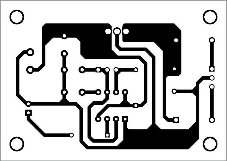
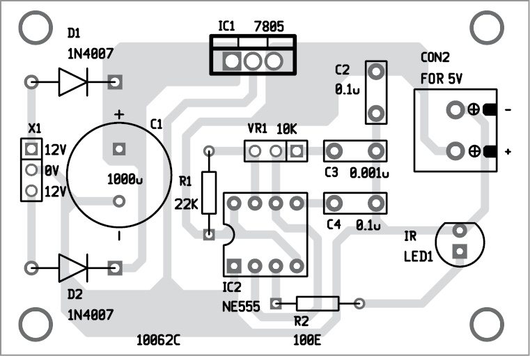
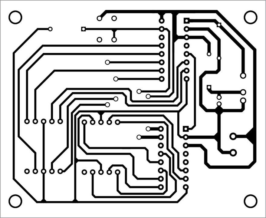
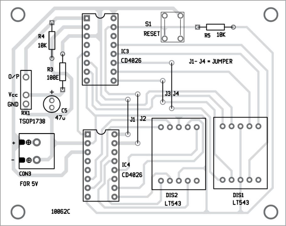
Download PCB and component layouts PDFs: click here
Install the transmitter and receiver units at the gate such that IR beam of IR LED1 falls directly on the IR receiver RX1. Whenever a person crosses the gate IR beam is interrupted. Each intterruption generates a clock pulse in the receiver unit, which is registered as a count and is displayed on the 7-segment displays.0
Feel interested? Check out other electronics projects.

Why exact 38KHz is needed to be generated? kindly explain.
TSOP1738 works on 38kHz frequency. Therefore the carrier frequency generated by the transmitter circuit should be around 38kHz, otherwise the signal will not be received at the receiver circuit.
Any contact or email address
Hi, what if tsop 1738 doesn’t available in the market is there any alternative components that we could used?
The IR receiver TSOP 1738 continuously receives the clock signal and then outputs it to the counter. And no matter what it continuously displays the value for 1,2,3,4,5,6,7,8,9 and then returns to 0 regardless of the interference. It will be continuously. How do you explain that? Please answer fast…
Infrared(IR) sensor has inherent false triggering problem if exposed to light sources such as tubelight, sunlight, etc. Firstly, make sure that your TSOP1738 IR sensor module is not exposed to such light sources and also make sure that there are no electrical sparking near your circuit. Secondly, you can use a 470UF, 25V electrolytic capacitor across pin 1 and 3 of TSOP1738.
You can also try by covering the TSOP1738 with a suitable enclosure, make a hole on its front portion inorder to receive IR light from the transmitter side. If the problem still persists, replace TSOP1738 with a fresh one.
I built this circuit but used CD4033 instead of CD4026. Even though the pulse is interrupted the 00 display remains and there is no counting. But when interrupted there is a 1Volt pulse on PIN 1 of 4033. Yet is does not start counting. When I put 5v straight onto pin1 it started to count. Is the 1volt from TSOP1738 too low or is that normal. What should I do ?