


The first part of the series discussed the implementation of I2C controller using an FPGA. The focus in this part is interfacing FPGA with LCD. The basics of LCD operation, hardware interconnection and VHDL code along with its description are presented here.
LCD operation
Liquid crystals are materials that exhibit properties of both solids and liquids. These can be classified as nematic, smectic and cholesteric. Nematic liquid crystals are generally used in LCD fabrication with the twisted nematic material being the most common. Fig. 1 shows the construction of a twisted nematic LCD display. As we can see from the figure, it comprises a cell of liquid crystal fluid, conductive electrodes, a set of polarisers and a glass casing.
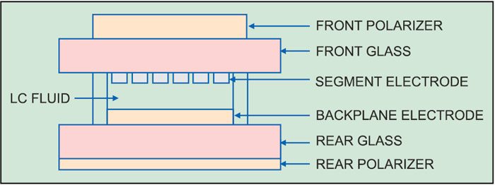
Polarisers are components that polarise light in one plane. On the inner surface of the glass casing, transparent electrodes are placed in the shape of the desired image. The electrode attached to the front glass is referred to as the segment electrode and the one attached to the rear glass is the backplane or the common electrode. The patterns of the backplane and segment electrodes form the numbers, letters, symbols, etc. The liquid crystal is sandwiched between the two electrodes.

An LCD controls the transmission of light by changing the polarisation of the light passing through the liquid crystals with the help of an externally applied voltage. As LCDs do not emit their own light, backlighting is used to enhance the legibility of the display in dark conditions. Backlighting is done using incandescent lamps, LEDs or electro-luminescent lamps.
LCDs have the capability to produce both positive as well as negative images. A positive image, defined as a dark image on a light background, is produced when the pixel that is ‘off’ is transparent and a pixel that is ‘on’ is opaque. In these displays, the front and the rear polarisers are perpendicular to each other.
A negative image is a light image on a dark background and is produced when a pixel that is ‘off’ is opaque and a pixel that is ‘on’ is transparent. This mode is typically used only when there is a backlight and the ambient lighting conditions are medium to dim. In these displays, the front and the rear polarisers are aligned to each other.
LCDs can be classified as direct drive and multiplex drive displays depending upon the technique used to drive them. Direct drive displays, also known as static drive displays, have an independent driver for each pixel. The drive voltage in this case is a square waveform having two voltage levels, namely, ground and VCC. However, as the display size increases, the drive circuitry becomes very complex. Hence, multiplex drive circuits are used for larger displays. Such displays reduce the total number of interconnections between the LCD and the driver. These have more than one backplane and the driver produces amplitude-varying, time-synchronised waveforms for both the segments and backplanes.
LCDs are non-emissive devices, that is, they do not generate light of their own. Depending upon the mode of transmission of light in LCDs, these are classified as reflective, transmissive and transreflective displays.
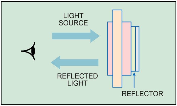
Reflective LCD displays have a reflector attached to the rear polariser which reflects incoming light evenly back into the display. Fig. 2 shows the principle of operation of reflective LCD displays. Such displays rely on the ambient light to operate and do not work in dark conditions. These produce only positive images. The front and the rear polarisers are perpendicular to each other. Such displays are commonly used in calculators and digital wrist watches.
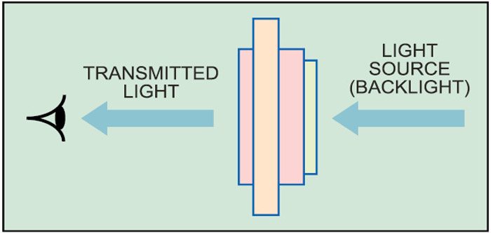
In transmissive LCD displays, back light is used as the light source. Most of these displays operate in the negative mode, with the text displayed in light colour and the background in a dark colour. Fig. 3 shows the basic construction of a transmissive display. Negative transmissive displays have front and rear polarisers in parallel with each other whereas positive transmissive displays have the front and the rear polarisers perpendicular to each other.
Transmissive displays are good for very low light level conditions. They offer very poor contrast when used under direct sunlight because sunlight swamps out the backlighting. These are generally used in medical devices, electronics test and measuring equipment and in laptops.
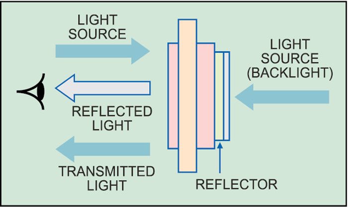
Transreflective displays are a combination of reflective and transmissive displays (Fig. 4). A white or silver translucent material is applied to the rear of the display, which reflects some of the ambient light back to the observer. It also allows the backlight to pass through. These are good for use in varying light conditions. However, they offer poorer contrast ratios than reflective displays.
